Tuesday 13 October 2009

Open-Source to the rescue!

To build anything in a RepRap, you need to have a 3-D design, save it as a STL or triangle mesh file, and load it into the RepRap host software (or skeinforge).

To create these designs, RepRappers use different programs - Either an adapted 3-d modelling programs, originally used for animation (like Blender and Art of Illusion), or freeware versions of CAD software (like CoCreate). These solutions work, and work well, but each program has seperate advantages. I've been looking out for a 'better fit' - a CAD-style program, that supports building meshes and solids.

Make magazine today furnished me with a link to FreeCAD.

It's pretty slick - either I'm quite lucky, or it works quite well. Within a few minutes I was able to load it up, get started, create a small cube model, export it to an STL file and import it successfully into the RepRap Host software (not always an easy thing!).

OK, lets give it a real test...

Let's load up some data from a complex file: a human head.
To really test it, I created a large sphere, stuck it on top, and did a 'union' (Join).
This is not nice: most complex geometries cause all sorts of bent and broken and backwards triangles. Lucky there is an analysis tool to point all this out:
From FreeCAD

Pressing some of the 'repair' buttons sorted all this out.
From FreeCAD

This exported easily to an STL file: and then loaded straight into the host software.

From FreeCAD


It started to slice and print to gcode : it got to 55 layers through before I got bored and turned it off.

FreeCAD is currently alpha software so far, but certainly one to watch!

Saturday 10 October 2009

One step forwards

G'day all.

I've been quiet recently - I had packed everything away into the garage as we were planning to move. Plans change, we're now not moving so I unpacked the RepRap and fired it up.
From ResistorHeater

First problem : blocked nozzle, due to a broken thermistor - overheated - and set the ABS solid.
Cleared down and drilled it out.

I replaced the thermistor with a spare 100k makerbot one - my last spare.

Interestingly enough, I soldered in a 100k thermistor from Maplins into a spare circuit, connected it up, and the temp read about 20C at room temp, and 34C while holding it - pretty good without any change in configuration. It might be a suitable replacement for the 'official' ones.

Replacement thermistor in, I warmed up the heater and 'let rip'
From ResistorHeater


It works! Extrusion is pretty slow (232mm/sec) and wide (nearly 1mm diameter through a 0.8mm nozzle) but it comes out reliably and pretty consistently. Temp was about 225C and power (screw thread/servo) at 180/255.

Now I have something working, I can refine the nozzle size ( I should be able to get some 0.6mm B&Q nozzles) and the original BfB 0.4mm nozzle, plus I have some small drills.

I now need to get my settings and speeds right in the host software - my current version is months old, maybe I should update. I've been thinking about upgrading to version 3 electronics, too, but with the excellent Mendel design out with a much smaller footprint, I quite fancy that. It might be time to build a Mendel using my Darwin....
:-)

Wednesday 2 September 2009

Balls to the rescue

Since I disassembled my MyVu Solo glasses, I've been looking for some optics to enlarge the image to a useful size. The stripped displays are only a few mm square.
From MyVu


I thought about trying a jeweller's magnifying loupe (the thing they use to look at gemstones), but they looked a bit heavy.

What I really need is some kind of curved mirror. After looking up in wikipedia, I reckon I needed a short section of concave curved mirror with a focal length of only a few cm. OK, where the hell do you get one of those?
Well, if you extend a curved mirror, you end up with a sphere. So, a mirrored sphere - a few cm across? Well, your local christmas shop!
From HMD


To cut a small square section, take a diamond-coated file and gently score the lines you want to cut....
From HMD

Or just explode it in you hands, like I did.
Taking a couple of the larger sections, the internal surface is pretty much mirrored. Too far away, and there is no image:
From HMD

But, at just over half the radius away:
From HMD

An enlarged, reflected image is formed. Since the glasses originally had plane reflectors in, I think it probably won't even need reversing - now to mount them in a test pair of glasses.

NOTE : safety warnings apply - don't play about with razor-sharp wafer-thin slivers of glass near your eyes. Like I am. If I stick glass in my eye it's my own stupid fault. Don't try this at home.

Laser Scanner

Not strictly RepRap related, but I've been playing with the David Laserscanner software from www.david-laserscanner.com/.

It does seem pretty useful for generating source data. If it's good enough, you can scan an item, tidy up the data a bit, then print it put on your RepRap. The system then becomes a 3-d copier.

So, is it up to the task?

Initial setup:
You need a webcam, a laser line (either a laser level or a laser pointer), and the software.

I used an old webcam (640x480), and a red laser pointer (5mW) from ThinkGeek - but they're pretty readily available.

The software comes with a few different templates - basically a dot pattern you print out. You then attach the pattern to two sides of a 90 degree corner - like the inside of a box, or two card sheets at right-angles.
From laserscanner

You then point the webcam at the box, and 'paint' it with the laser line. The webcam can see the shadow of the line on the object and the background, and can work out the 3-d profile of the object.

To turn a laser pointer into a line, you need to bounce it off a curved surface (I made a line with a shiny metal knife handle), or shine through a glass cylinder. Wandering around Bath, I care across a shop selling christmas decorations - and they had a nice glass raindrop - shape:
From laserscanner

Shining the laser through the glass cylinder produces a nice line:
From laserscanner

I snapped off a short section of the glass and polymorphed it to the front of the laser. I've now got a simple laser line.
Initial playing with the software gives an idea of the result - I think it needs a bit of careful configuration to get the best scans out of it, but the potential is definitely there.
From laserscanner

Quick-release extruder

I pulled out my reprap at the weekend and fired it up. After levelling the bed, checking calibration, and fixing the z-flag that was loose, I started the extruder....

Nothing came out.

After some fiddling, I disassembled and reassembled the heater/nozzle - it was fill of brown/grey ABS, absolutely rock-solid, and had to be drilled out.

Since this is about the 50th time I have disassembled/reassembled my heater/nozzle assembly, I tried a modification to make it easier to change. My PEEK insulator is bolted to a penny washer with an m8 thread and two half-nuts.
From quickrelease

I cut a slot in the penny washer and I can now loosen a bolt and slide the extruder barrel/heater out to change it.
From quickrelease


This came in really handy, because as I restarted, warmed up to 225C, and fed the ABS through - it stuck fast. At least I could disassemble to find the problem.

The ABS appears to form a solid plug of the brown overheat mess as soon as it hits the heater, going solid and blocking the tube.

I think I've got a broken thermistor, or maybe the heat transfer is bad. It seems to warm up as expected, and reports the right temp (ish) staring about 16C and rising to 225C - fluctuating about 223-226C, but the ABS is definitely overheating.

I'll swop it out with another one and see if that helps.

Monday 24 August 2009

MyVu Solo displays

Here's the photo of the bits remaining after breaking up the glasses:
From MyVu

The remaining useful pieces are two microdisplays with controller: one and one half-optics sets (I cracked one mirror).
From MyVu

I'd sliced the cable between the two PCBs during disassembly and found that they don't turn on if the second display is not connected, even with a bit of fiddling. Trying to strip the FFC (Flat Flexible Cable) to try and reattach it just didn't work - the connectors are about 0.2mm wide at that point and I just cut more and more off.
From MyVu

Farnell came to the rescue: A 20-way 0.5mm pitch FFC (A to A) for £1.54 did the job just as well. I plugged it in to both displays and they're both up and running.
Here's a mini southpark episode:
From MyVu


Now all I need are some glasses and some magnifying lenses....

Monday 17 August 2009

No disassemble - part 2

Just to finish off the breakdown of the myvu glasses:

Once the outer shell has been removed, you are left with a small plastic unit containing two clear plastic blocks, with the displays at either end. They appear to be solidly glued in.

I ended cutting the block in half using wire cutters. The plastic is moulded in two parts, but is pretty solidly attached or glued. I then had to cut away and snap bits with pliers to uncover the plastic prisms.
Once the prisms are removed, the remaining plastic can be snipped away to uncover the displays and tidy them up a bit. Be careful of the diagonal ends of the prisms - there are small glass mirrors glued to the ends, and I chipped one.

I now have two uncovered displays and two plastic mirror/lenses. They can be re-mounted in a more suitable frame (maybe reprapped?)

Sunday 16 August 2009

Another step forward

Dusted off the old reprap today.

I warmed the heater up and extruded a few cm of 1mm extrusion - through a 0.8mm nozzle, the print quality won't be too good but it should be quick. The extruder actually seems to work reasonably well!

I then had to fix the acrylic Z-axis flag, which has cracked and broken off - the flag holder and also the opto-endstop holder. A big lump of polymorph worked really well at replacing both cracked acrylic parts.

I then had a massive headache so I put it down for the afternoon.

Nearly there - time to try a print soon.

No disassemble Number Five!

Today I took apart a set of MyVu solo glasses to extract the displays. I thought it might be useful to post some photos to help anyone else following my path.
From MyVu

I built my own phono lead to connect a composite source - the cheaper version only comes with an Ipod lead. Pinouts for the myvu solo 4-pole 3.5mm connector are:

Tip - left
ring - right
ring - a/v ground
body/ring - video

This happens to be the same as the Zune media player. Connect the grounds (outer rings) from the phonos to the a/v ground, and the tips of three phonos to the left, right and video.

Starting point:
From MyVu


A bit of experimentation with the screwdriver found that the front cover is held on by a couple of plastic tabs, and with a bit of levering comes off pretty easy.

From MyVu

From MyVu


There is a plastic frame in three parts holding everything together. It is screwed together with four torx screws - two neat the centre bridge, and two behind small plasic covers forming the arm pivots (the hinges for the folding bits).
I drilled these out as my driver was too big, causing a bit of damage.
From MyVu


The signal is generated in the control box and fed up a many-core wire into a small connecting PCB on the left side of the glasses.
From MyVu

The signal appears to be split and sent across to the right-hand display using the (damaged) flat cable. This can be unplugged at both ends. The right-hand end is simpler, only connecting to the right ear piece.
From MyVu


I cut the earphone wires and pulled out the rubber housings from the arms. This allowed me to force the left arm apart freeing the cable.

Currently, the control box still works, although the video is not visible. I think it's because the backlight circuit probably runs through both LEDs in series, so I'll need to identify and patch that so I have a single working, monoptical display. Then I can re-mount it in a more 'socially acceptable' frame to form the HUD for my dataglasses.

Sunday 9 August 2009

DataGlasses

I spent a few hours this weekend working on another project...

I've been interested in HCI (Human-Computer Interaction) for a while - it started as part of my job - and I got started with alternative input devices, mainly keyboards and mice when I suffered from RSI/carpal tunnel.

When I read about dataglasses (courtesy of the most excellent writer Charles Stross) I was fascinated. I wanted some. They sounded like such a good idea - a logical extension of wearable computer use, a real integration of the things computers are good at to provide a useful tool.

For the uninitiated, dataglasses are basically sunglasses with an integrated computer display - providing a head-up display - add in net access, camera to provide face recognition, clever software, and you start to get some really cool capabilities. I'll leave it to Mr. Stross to explain the details (and possible problems) in his book Accelerando.

Since no manufacturer seems to be producing them yet, I'll have to build my own.

Components:
MyVu MA049 Solo Plus personal media glasses
Old laptop with composite video out
An iphone headphone adaptor plug (Any 4-wire 3.5mm plug will do - like a normal headphone plug but with 3 divisions not 2)
Two or more webcams.

Phase 1:
Get the computer display onto the glasses display.
Actually a bit harder than it sounds - the glasses only come with an Ipod lead (at least the £45 I bought on ebay) and the extra connectors kit is out of stock. It's basically a 4-pole 3.5mm stereo jack, like a headphone plug, to phono plugs.

I found an 'iphone' headphone adaptor in a charity shop which had a 4-pole 3.5mm plug - so a bit of modding is in order.

I investigated the output from the Ipod lead and I think I've sorted the signals.

MyVu Solo plus pinout
4-pole 3.5mm plug

Tip - Left
Ring 1 - Right
Ring 2 - A/V Ground
Ring 3 - Video

I've hooked up the wires with some of my shonky soldering, but it's refusing to play ball so far. The glasses claim to be missing the video signal.

It's still a work in progress....

Monday 27 July 2009

Doorstop Heater Block

Wandering B'n'Q the other day, I checked the bargain bin and found this:
From ResistorHeater

It is a brass doorstop: Basically a 1 inch brass rod with a M6 threaded hole down the centre. It's just about the right size to make a heater block! And, it's reduced to £3!
I picked one up to play with.

Closer inspection revealed that the central threaded hole projects all the way through the block, stopping at the small indent for the O-ring.

I hacksawed through at the indent, cutting off a 20mm chunk - the m6 thread goes right through.
I drilled a couple of 6.5mm holes through for my resistors - and widened them a little, as my resistors are not straight, and added a small hole for a themistor.
Widening half the m6 thread to m8 allows me to screw in a Peek insulator.
From ResistorHeater

Here's a pic of the components:
From ResistorHeater

and assembled:
From ResistorHeater

Firing it up, I found that it reaches 220C in about 7 minutes, with no insulation. The heater seems pretty sturdy and well-attached. Starting up my (fixed) BfB extruder drive, I waited expectantly....
From ResistorHeater

Hurrah! It extruded several cm of filament - reasonably quick too!

If it starts up again later, then I might be able to build something soon!

Extrusion: 220C at motor speed of 120/255. Nozzle 0.8mm welding tip, 1.01mm filament

Fings I av Fixed.

Since starting to build my RepRap, I've fixed much more around the house. Having the tools to hand, and having the confidence to try, means that I've fixed things where previously I would have thrown them away.

I've replaced the power plugs on two of our laptops several times.
I've fixed one of the laptops - including disassembling it, taking out the main PCB, de-soldering and changing over two SMT microswitches, and replacing the power socket.
I've fixed a couple of battery-operated kid's toys - simple things like disconnected wires and broken solder joints.
Recently, when the telephone cable was accidentally cut during some gardening, I replaced the whole section of cable - the old cable was past it, not worth joining.
I fixed a doll's arm back on.
I fixed the bathroom door lock - and several other jobs in the home, mainly because the tools were available and handy.

Also, I taught my daughter to solder - making a 'game of life' kit together. It went really well, and worked first time!

All this (indirectly) because of my RepRap.

Heater Blocks

In my quest to ignore conventional wisdom and make my own extruder, I've started playing around with resistor heaters in blocks like NopHead.

I looked around for a while, and found a mild steel block (30x30x10mm) at my local engineering suppliers. They also supplied me a couple of 1 inch (25mm) cubes of copper.

With one of the steel blocks, I drilled two 7.5mm holes laterally and filled them each with a resistor wrapped in tinfoil to provide a tight fit (and better heat transfer). I drilled a 5.5mm hole through the block and tapped it to M6 thread.
From ResistorHeater
With an M6 welding tip, I extended the m6 thread to all the way down the barrel. Then, drilling it out to 3.2mm, I made a mistake and drilled it all the way through. I now had a short copper tube with m6 outer thread. This screwed through the heater block, leaving 5mm top and bottom. The existing BfB nozzle screws nicely onto the copper thread.

Screwing a m6 coupling nut onto the top allows me to connect a drilled stainless steel bolt. Stainless steel is a poor conductor of heat - not as good as PTFE insulation, but helps stop the heat transfer up the shaft.
From ResistorHeater
Firing it up, there is a lot of thermal inertia - it takes a while to get going (2-3C per second). It finally tops out at 210C without any insulation. The stainless is not a brilliant insulator - it gets fairly hot (70C) at the washer/support end, but should be usable.

Tuesday 21 July 2009

Learning more and more

I've been building more nozzles and drilling some holes in metal. I tried drilling out a stainless steel bolt to make the extruder barrel, but it was hard work and didn't feel right. Usually when that happens, I'm doing something wrong...
So, I googled and read up on drilling into stainless steel.

Apparently, when the drill rubs over the metal in the hole, it starts to heat and work harden a thin layer of steel - making it harder and stronger - and more difficult to drill.

The advice is to drill at a slow to medium speed, apply lots of pressure, and drill few mm then pull right back to clear the swarf. This is pretty much the opposite of my original technique.

This works *really* well - you get lovely long spirals of swarf (razor sharp splinters) and the hole is much easier to drill. I found it much easier to drill out welding tips and have drilled a couple of stainless bolts using the afghan lathe technique.

Top Tip: Read instructions before using.

Thursday 11 June 2009

BitsFromBytes extruder

Reading a comment on the RepRap forums I *finally* realised that BitsFromBytes had a Forum and a separate Blog. Since I've got an older v2 kit, I hadn't checked back there for a while.

While catching up on the blog, I found a really useful post by Tony (copied below):
MK2 extruder
I was able to get some very nice results from the original GM3 powered BFB extruder, all the same principles apply, keep the melt zone short and support the PTFE close to the heater. Stability of the motor speed and the quality of the motors were the only slight issues. I ran both single and twin motor versions for many months without a problem. I still believe this original extruder design is very good and it certainly proved itself reliable over that time.
For those who had problems getting them to work I strongly suggest you blueprint the design exactly as it should be, by all means sharpen the thread and undercut it with a hack saw if you must but this should be the limit of the mods. The most common error I have heard about is the omission of the small reaction washer behind the main feed screw. Miss this out and you will never grip the filament tight enough. Build the extruder exactly as the instructions and it works, mess with the PTFE add custom heaters and coach bolts for the drive screw(what!), and you are in unknown territory. Run it how it should be first, get some experience in printing, you will then start to see where modifications would pay dividends, the original one works very well and starts reliably from cold.

Coach bolts? Who would do such a thing! :-)

Time to re-check. If it's only me and one or two others having problems with the BfB drive, then it's probably either my setup or incorrect assembly.

Re-state the problem.
Initial problem: heater/motor control worked fine, but extruding at 250C and any speed only resulted in 2-3mm/minute, almost too slow to see. Tried various temps and speeds, same result.
Removing heater, I was able to manually pull the filament through (screw thread not biting).

Tightened all the bolts - still no change to extrusion. Tightened to the point the acrylic started to crack (on the 2mm plate holding the bolt/filament roller). No change. Springs fully compressed. (reaction washer in place)
Disassembled, sharpened bolt thread with die. Better grip, but no better extrusion.

Examining the heater and drive separately, found that the heater required a reasonable force, but extruded OK, but the drive system still wasn't strong enough - although it seemed more than strong enough during testing, it still wouldn't extrude.

I then experimented with some different nozzles and drive systems. I found some nozzle designs needed less force, but needed careful machining to be reliable.
Replacing the m8 thread with a coach bolt , which had a much larger, sharper thread really gripped the filament very well - but still didn't extrude. WTF?

I think the problem is the thread is very grippy - but the pitch is about 4 times larger than the m8 thread. The coach bolt drive is very strong, but drives faster than the m8 thread - a few mm per revolution. I think pushing too fast chokes the extruder, stalling the filament, and stripping the filament (confirmed by examination). It might work very well, but needs to be geared slower (or driven by a stepper).

OK, so after reading the BfB forum and posts, I stripped down my extruder to have a closer look.
A careful inspection of the extruder parts revealed this:
From BfBExtruder
The heater bolts are *slightly* too large for the channels in the extruder drive, causing a gap between the plates. This meant when I removed the heater to check the drive system, it closes up - and the drive works properly. When I screwed in the heater to check the extrusion and bolt to the reprap, the bolts screw in - the gap opens - and the pressure is taken off the screw thread. The screw doesn't bite the filament, and doesn't pull it through.
Bugger.

I'll file the channels out, reassemble to the original BfB extruder, and try again. I think it *might* just work this time (famous last words...)

As we say in computing, PICNIC (Problem in chair, not in computer)....or should that be PIANID (Problem in Assembler, Not In Design)...

Tuesday 9 June 2009

Presentation over!

Today I managed to show my RepRap to 50+ colleagues at work (IPL).

We have a lunchtime talk every few weeks, on technical and non-technical subjects, given by staff and invited contributors. I foolishly volunteered to give a presentation on my RepRap.

I put together a little presentation, some notes and delivered it today!

It went really well. Everyone was attentive and I got some sensible questions, so some of them were listening! After the talk, I started up my RepRap and it ran through a dummy print, since my extruder isn't quite working at the moment.
Lots of people stayed to watch, and there was some lively discussion over what could be printed, and everyone seemed interested.

As usual with presentations, you get really nervous before, but after a couple of minutes that goes and I really enjoyed showing off my RepRap.

To IPL'ers, thanks for listening and showing so much interest!

Top Tips for improving my presentation:
Lots of questions on possible materials and what could be printed (i.e. overhangs, support material, etc).
Concentrate on the 3d-printing of other objects and introduce the self-replication as a side-effect: Also need to mention upgrading itself using printed parts

Sunday 31 May 2009

Tips, Tips and more tips

I've recently ended up with a whole bunch of welding tips and some tattoo tips.
I thought it might be interesting to compare them.
From RepRap_bits
Sources:
  • Halfords SIP Welding tips, 0.6mm or 0.8mm hole, M5 thread - 5 for £4.99

  • B&Q, MIG Contact tips, 0.6mm or 0.8mm hole, M6 thread - 5 for £4.99

  • Ebay, Tattoo tips, various sizes, no thread - 18 mixed for approx £10. can be bought singly.
From RepRap_bits
Halfords are the smallest : an M5 thread, and a short body (18mm). B&Q have a larger M6 thread and are nearly 24mm long. Both welding tips are copper, and the tattoo tips are stainless steel. The tattoo tips have a long barrel, but a huge hole for a rubber band in the side. (white line is 3mm standard ABS filament)
From RepRap_bits
The nozzle holes are all similar sizes. the first two are 0.6mm Halfords. The next two are 0.8mm from B&Q. The tattoo tips come in various sizes. These are the two smallest round holes: I think they're designated R1 and R2, and look to be a similar size to 0.6/0.8mm. Some of the tattoo nozzles are much larger.
From RepRap_bits
The shapes are very different: the Halfords tip has the 'best' shape, a 45degree taper. The B&Q has a flat tip - it might cause the extrudate to stick, although it would be easy to reshape with a drill and file.
Both the welding tips need to be carefully drilled out - typically 3mm - to within a whisker of the exit hole - so that the thin section is as short as possible.

The tattoo tips seem to be made by drilling a 6.8 or 7mm hole, then a 2mm? hole right through - then a tube of the required dimension is (brazed?) attached to bring the diameter down to the exit hole, and the tip shaped(guessing). From visual inspection, it looks like the 2/2.5mm hole extends almost all the way to the tip.
From RepRap_bits

I think that if the excess tube is 'trimmed' it will form a good nozzle shape internally.
The tattoo tips need to be attached and/or the big hole in the side sealed. a few initial thoughts are:
  • tap the internal diameter and screw in a standard reprap drilled bolt
  • cut an 8mm thread in the outside and screw into a coupling nut or threaded block
  • drill a 'heater block' like nopheads to 8mm and press-fit/solder/braze the tube to form a good seal.
I'll have a play with them (I've got 18, so plenty of spares) and see if anything works.

Of course, if 0.6 or 0.8mm is too big for you, you can always use the nichrome wire/high temp solder trick to get a smaller exit hole.
Since solder is a generally softer, has anyone tried blocking the hole and drilling the solder with a small drill bit to get a 0.4 hole?

Saturday 30 May 2009

Hacked Firmware for simple encoder

I've started hacking the firmware to add support for my simple speed controller.

Current version is here:

http://sites.google.com/site/renoirsrants/reprap/software-i-use

Warning: this is straight off my development version. Read (and modify) before using.

speed 1 = fast
speed 255 = slowest

It *should* run encoder at a constant rate.

Wednesday 27 May 2009

Finding parts

The key to finding RepRap or RepStrap parts: keep your eyes open, and don't be afraid to ask: experiment, try things out, and tweak your design to what you can find. I've found a few useful bits over the last couple of months.

I wanted to add an encoder to my GM3 drive motor, but I've previously blown my three spare opto-switches.
Asking around at work, I found an old ball mouse with a broken USB plug, and got permission to take it home from sysadmin.
Logic dictated that running off USB (5v) it might contain some opto-switches that I could recycle. Taking it apart, a quick inspection revealed two components either side of a slotted wheel that looked right:
From RepRap_bits


I desoldered them, ripped out the broken IR sensor from the x-max endstop board, and just soldered them in.

From RepRap_bits


Hooking it up to the arduino, it works perfectly!

Other extruder bits:

I found some thin-walled alumininum an brass tube in a Model shop in Westbury. It's imperial (5/32) but the internal diameter is exactly right for my 3.1mm filament.
From RepRap_bits

I think it might work well to make vik's no-lathe/ariel extruder, or to make a Nophead-style thin-walled extruder. I've got a large heatsink from a core2 CPU to go with it.

I've been looking for a block of metal to make nophead's resistor heater for a little while - it's not something you can buy in B&Q, and I don't happen to have aluminium bar stock in my garage. :-)

In the middle of Bath, down by Sainsburys, I walked past a little tool shop that was selling scrap metal outside. I went in and asked, and...
From RepRap_bits

Hey presto, the chap disappeared out the back and came back with a 10mmx30mm bar - and cut me off a couple of 30mm lengths from it. The best bit : cost 25p. So, a shout-out to the guys at Avery Knight and Bowlers, Bath - thanks guys. They've been consistently helpful and the shop is full of tools and other useful bits. I also grabbed some m6 coupling nuts - might be useful to attach nozzles - and a 7.5mm drill, which is the right size for my resistors.

I've thrown a few quid away on some tattoo tips from a dodgy overseas company (like these ones). I wanted to have a look to see if they would be useful to turn into nozzles. When (if) they arrive, I'll post some measurements and photos.

Edit: half-hour after posting this, I noticed a big split in the mains cord insulation for my wife's hairdryer. 'It's not safe, we'll have to you get a new one' - of course, nothing to do with the fact it's full of nichrome wire....

Tuesday 26 May 2009

Radio Renoir back on the air!

Sorry it's been a bit quiet recently, I've been off work with depression. There's been a lot going on in my life, and it all got a bit too much. However, the doc gave me some stronger tablets and I'm back to full form! Everyone's been really supportive, work have been great about it, really understanding (thanks D and J).
While I was low, I wrote a really rambling, bizarre post that make no sense at all, trying to explain. Glad I didn't post that one!

Very little progress made on the RepRap in the last month. However, I'm putting together a talk for my work colleagues on 9th june, so I'll post a copy of the presentation when I'm done. I'll also write up the couple of tweaks I have made, and some new bits I bought today.

BRB

Thursday 30 April 2009

Extruder design thoughts

I'm going to throw down some random extruder thoughts, untested theories, and probably re-iterate most of Nophead's proper research. I apologize for any complete rubbish or plagarism

ABS

ABS isn't really like chocolate, or ice, which is a simple solid or liquid.
When cold, it's solid and can withstand quite a lot of force in compression. This allows us to force it down a tube and use it a bit like a rod or piston to force the plastic into the nozzle.
When it warms up, you can bend it easily.
Warm it more, and it starts to soften. Because it's being pushed down, when it gets soft it tries to get wider, pressing against the sides of the tube. At some point, it becomes 'molten'.
'Molten' ABS isn't really liquid. In some ways, it's like plasticine or clay - it needs to be forced through a nozzle, it doesn't really 'flow'.
It's also a bit elasticy at times - when you stop pressing down, it can dribble on slowly for a bit, until it's evened out the pressure.
And finally it's a bit like melted mozzarella - pizza cheese. Pull the melted filament out of a heater, and you often get a really long, thin stringy bit - just like a Domino's advert.

Designing an extruder


Lots of my extruder designs have worked to a greater or lesser extent. It's not *too* hard to make an extruder work once, it's reliability and repeatability that cause my problems.

A larger heater chamber (4mm/5mm diameter) works OK, but the extra ABS takes longer to warm up and melt.

The shorter the 'melted', hot section the better, - preferably as near to the nozzle as you can get. Also, the less metal you have, the less thermal inertia you have, so it heats up quicker. The quicker it heats up, the quicker it cools down while extruding - so the heater power has to be controlled.

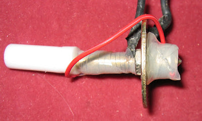
PTFE is a good insulator, and it's easy to machine - you can cut an 8mm rod with a sharp craft knife, and it's easy to drill. You can cut a thread easily with a bolt or nut. PEEK is much stronger and requires proper machining - use a tap/die to cut threads.

PTFE is soft, and when it's hot it gets softer, so it really needs extra support (external bolts and washers, etc) to hold the join to the heater barrel still, and extra pressure to avoid leaking plastic out the side. 8mm PEEK rod is strong enough to have a welding tip screw-in (tap an m5 thread) and easily holds the pressure.

The join between the barrel and the insulator is very important. This is where the ABS becomes softer and the filament will get wider and fill any gaps in the channel.

Quite often, my extruder experiments work the first time, but after cooling and re-heating are much stiffer and difficult to get restarted. After inspecting the cold filament, this is because the ABS flows into any small gaps and then solidifes when cold. The entire assembly will then be stuck until the gaps have melted.

If the extruder is hot but not flowing for a long time, the heat will flow up the ABS, softening and widening it further up into the insulator. At least PTFE is very slippery and it helps getting it restarted.

I think NopHead's design, with the thin aluminium tube insulator, excellently avoids the join problem. If you can cool the barrel further up, so that the melt occurs inside the barrel, this problem doesn't occur.
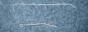
Nichrome / Resistors


Both Nichrome wire and resistors both work reliably and reach the temps needed. Nichrome wire needs more preparation and a layer of insulation - Fire cement, jb weld, or Kapton / kraken tape. If you connect your normal wire to the nichrome by knotting it, or using a crimp connector, it's much easier to wind on and you can hold the join safe inside the fire cement or tape. Nichrome is very flexible, you can wind it on the barrel, nozzle, or both.

Resistors are nice, self-contained heaters. They work well, but you need to transfer the heat from the resistor surface to the nozzle. This means either embedding it in a drilled block (like NopHead) or my low-tech solution of shoving them inside m8 coupling nuts (as I don't have any solid blocks lying around). Either way, they're larger and need more metal (therefore more thermal inertia, slower heater), and not quite as flexible as the assembly is big and chunky compared to the nichrome wire.

Both methods work well.

Nozzles
Ideally, the nozzle should be removable.
Ideally, to keep the heated section as short as possible, the heater should be close to or on the nozzle.
Both of these requirements can conflict :-)

Welding tips (0.6mm) from Halfords, £5 for five, work pretty well as nozzles or even combined barrel/nozzles. They need to be carefully drilled out to 3 or 3.2mm almost to the end, but be careful. I've wrecked four trying to drill to 3.5mm to get a better heater entry, the walls are just too thin. The central hole helps align the drill centrally, even drilling by hand works OK, but I'd use a 1mm then 2mm then 3mm bits first.

I've had reasonable success with a PEEK insulator, a welding tip, with nichrome wire wound directly round the welding tip.


Have a go and see what you think :-)

More Extruder Experiments

Time to write up the past few weeks of experimenting in making extruders:
From Renoir6_Extruder
This is a quick extruder made from a short section of 5mm brass tube, 8mm PTFE rod with a central 3.2mm hole for the filament and an experimental PTFE nozzle.
The PTFE is drilled about 8mm in to 5mm diameter, and the tube is push-fit into the PTFE.
The nozzle is made from 10mm PTFE rod, drilled almost to the end with a 5mm diameter. Part of the outside is shaped down to 8mm (to fit a large washer for support) and tapered a bit. The final breakthrough was done with a .35mm hand drill where the PTFE is about 2mm thick.

The heater is made from a couple of layers of kraken tape and some (partly) insulated nichrome wire reclaimed from a previous nozzle.

Warming this barrel up, the tape didn't appear to be affected, so I fed some ABS down. it seems to melt fine, filling the 5mm brass easily, but I hadn't bolted it down properly to hold the PTFE together, and I pushed the nozzle off before it came out the 0.35 hole.
From Renoir6_Extruder
It had been at 220C for a half-hour or so, so I deconstructed it to see if the kraken tape was damaged:
From Renoir6_Extruder
It seems to be unaffected. The covering you can see on the nichrome is the original insulation: it seems to decompose and can easily be scraped off with fingers, but even where the nichrome is just bare wire the kraken tape is unaffected. This isn't a long term test, but it's promising.
From Renoir6_Extruder
This extruder uses a brass tube, and a PTFE nozzle and insulator as above, but uses a different heater. Two wirewound resistors are placed inside M8 coupling nuts. The nuts are then held together in a vice and a 5mm hole is drilled between them.
The two coupling nuts can be placed around the brass tube (or even a welding tip) and held together with tape. you can also pop a thermistor between the tape and the nuts for temp monitoring.

To provide pressure to the PTFE tube joints, a large m8 washer is placed over the nozzle (10mm PTFE rod turned town to 8mm) and bolted to the existing BfB extruder drive (using the enhanced coach bolt drive).

From Renoir6_Extruder
This warms up fine to 220C and extrudes with some force. This PTFE nozzle has a 0.6mm hole, about 0.5mm thick PTFE (thin enough to see light through) but is still able to contain reasonably high hand forces. It extrudes, slowly, but immediately expands to a much larger extrusion.
From Renoir6_Extruder
Eventually I decided to re-build a more traditional extruder. A couple of taps with a hammer broke up the fire cement and allowed me to reclaim the nichrome, m6 BfB barrel and nozzle.
From Renoir6_Extruder
Using a combination of learning from my experiments, I've built yet another version:
From Renoir6_Extruder
3ohm nichrome heater directly around the nozzle, and 4ohm above. PTFE screwed to nozzle and also secured using bolts and washer. Washer heat isolated using a turned PTFE washer - also holds the m6 barrel nicely in the m8 washer. kraken tape insulating the heater. Coach bolt hack on a BfB lasercut extruder drive, standard GM3 DC motor/gearbox. Standard BfB aluminium nozzle.

I'll see how this one performs soon... :-)