Sunday 20 November 2011

Hand-drill geared extruder

I managed to break my original BfB extruder :-(. The acrylic had flexed too many times, and the top retaining bracket broke in half. The screw thread now carefully unscrews itself rather than driving the filament down :-(

So, time to update to a modern wade-style or similar extruder, using a hobbled bolt. Of course, I could have bought the gear drives from the many RepRap shops or ebay, but that's too easy :-).
Instead, I found an old cheap hand drill, with similar sized gearing. It turned out to be on an 8mm shaft.
I added a 5mm to 8mm sleeve to a stepper motor (made from a sex bolt)  and drilled and tapped a 4mm hole for a grub screw - I could then attach the smaller gear to the stepper shaft. The larger gear I cut a small square indent to match a carriage bolt, and cut some teeth into the threads using a dremmel cutting disc. A plastic cutting board and an Ikea bracket made a mount, and three skate bearings (8mm 908) made up a channel for the filament.

It's not pretty, and it's heavier than ABS gearing, but it grips the filament like anything - I can't stop it using my full strength grip, and really forces the filament through. 

I'm currently building a heater block and nozzle to add on the bottom. Hopefully this 'RepStrapStruder' will last long enough for me to print a proper wade's extruder. 

Thursday 10 November 2011

New Megas

My new Mega boards arrived - all good.
Simple tests worked fine, but after uploading the RepRap host software at 115200 Baud, had problems connecting and even uploading new sketches. I had to press reset and upload almost straightaway, otherwise the upload failed.

A bit of research suggested an updated Atmega 8u2 firmware (the usb chip). (also the new boards appear as /dev/ttyASM0 instead of /dev/ttyUSB0 - update to the latest RXTX libraries.

Borrowed from a forum post by stimmer on this thread

I saw that a new Uno firmware had been uploaded to the Arduino repository. I've been trying it out, it seems pretty good so far, tools menu and serial monitor are much more reliable and it only failed to program once. (Although the Duemilanove was never perfect either)

I got the firmware from here:
https://github.com/arduino/Arduino/tree/master/hardware/arduino/firmwares/arduin...(click on the right firmware, then click raw, then save it)

Reflashing the firmware on the 8u2 is a little tricky. Don't try this unless you are prepared to risk bricking your board completely!

You need the dfu-programmer utility:
sudo apt-get install dfu-programmer

Then follow the instructions here to get the Uno into DFU mode:
http://www.arduino.cc/cgi-bin/yabb2/YaBB.pl?num=1285962838/10#10

Then to flash the firmware, do this:
sudo dfu-programmer at90usb82 erase
sudo dfu-programmer at90usb82 flash --debug 1 Arduino-usbserial-uno.hex
sudo dfu-programmer at90usb82 reset

Finally unplug the USB plug, wait a few seconds, plug back in.


Also, a good page on the arduino site

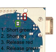
Note, that to put reset the Mega 8u2 chip, the reset pins are a bit different: I found instructions for resetting the mega chip.


My mega's accepted the sketches without problem, and both replicatorG and RepRap host connect well at 115200 baud.

Might help if you're getting unreliable high-speed connections to the arduino and you've got a recent board (/dev/ttyACM0)

Tuesday 1 November 2011

Arduino Mega board is toast!

I have managed to blow my Arduino mega board.
It stopped uploading, and there was a 'hot' smell - never a good sign. Unplugging everything, the arduino chip was very hot indeed.

After waiting for it to cool, I found that plugging it into the USB socket - nothing else - started to make the mega chip warm up, and it got too hot to touch. :-(
Another circuit board is sacrificed to the gods of knowledge and experience.

Tracing things back, I wondered how it happened. My setup hadn't changed, I'd just been running heater and extruder tests - the steppers weren't plugged in, so it was unlikely to be them.

Looking at the my heater board again, I realised that the output pin of the arduino was connected straight to ground through the MOSFET gate - no current limiting resistor. A bit of digging uncovered a possible problem - the design I'd used as a base (RepRap Gen 2/3) had the same circuit, but used current limiting Mosfets. I'd upgraded mine to larger ones, but checking the data sheet, the Mosfet gate acts a bit like a capacitor. Charging the gate could be done slow(with a resistor) or fast. A current of 2A was given as an example to charge the gate in 14nS.

Oh. The arduino pins can only handle 100mA or so. Still, it only does that when it's switched on or off, so long as I wasn't switching it on and off thousands of times a second - like using PWM.... Damn.

Looking back, it's surprising that it coped as well as it did - it should have gone up in smoke straightaway! I'm impressed it worked at all  - it coped for several hours of testing. Each time it switched, the arduino pin was directly connected to ground - drawing a big current for a few mS, then when it switched off, the mosfet gate would discharge itself straight through the arduinio pin to ground.

I have now redesigned my heater / Mosfet board to incorporate a 560ohm current limiting resistor (between the arduino pin and the mosfet gate), and also a pull-down 100k resistor between the Mosfet gate and ground. It should limit the current to 90mA, and make sure the gates switch off if the board isn't connected.

I've also ordered a couple of new Ardunios - hopefully I'll be more careful with these...
:-)

Sunday 30 October 2011

Recycling!

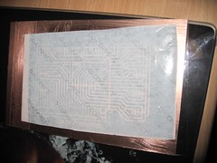
I've been using the laser toner method for a while to make my PCBs. It seems to work well for me, I print out the PCBs using a  Samsung ML2010 laser printer, tape them to a cleaned copper board, then run them through a laminator twice. The heat fuses the toner to the board, and as long as your paper isn't too sticky, you can peel it straight off and etch.
Sticker backing PCB
I've been using this successfully, even for larger boards like my Arduino mega shield. The key variable seems to be the paper. I have the best results by cutting a square of sticker backing paper, using the stickers to stick it to the centre of a normal sheet of paper, then printing the PCB from Eagle. This works well, but I do need a sheet of stickers (like the A4 laser printing stickers) every time.

Other people have reported success with tracing paper, or magazine paper. I grabbed some tracing paper (two types, Goldline 63gsm and Goldline 112gsm) paper and gave it a try. It printed well, but didn't stick too well - you need to soak the paper to remove it, and most of my toner came off with the paper. Maybe my laminator wasn't hot enough :-(.

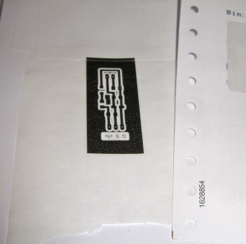
So, I'd run out of labels, my tracing paper experiments weren't working well - and then my eye fell on a discarded Farnell packing bill on my table. The Farnell packing receipts are printed on some sort of fan-fold sticker paper so that the address labels can be removed and stuck to the box. The whole bill is basically one big sticker! I cut a square, stuck it to a sheet of paper using the sticker I'd just removed, and ran it through the printer.
Farnell label

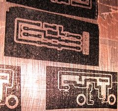
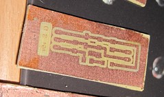
Perfect result, first time!  The toner transferred very well to the board:
Farnell stickers work well

Etched farnell board - success

The finished board (a SMT version of the tiny thermistor circuit) looks great and from the detail (on the lettering) this would work with much finer traces!

I'll start saving up all my old shipping receipts instead of buying printer labels now....


P.S. top tip - after the stickers have been 'laminated' and cooled, if you gently rub the back of the sticker with your thumb, a small 'bubble' forms that gently lifts the sticker backing away from the toner bit by bit. I get almost 100% adhesion with this technique.


Crimptastic!

After a few days, my new crimping toys tools arrived in the post. Here's a joint from a couple of years BC (Before Crimptool) :
First attempt at crimp connectors
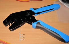
However, that was before the RVFM HT-225D, which I got from Rapid.
RVFM HT-225D
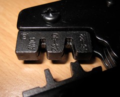
It has the correct 'B' shaped jaws to make proper crimp joints:
B-shaped jaws
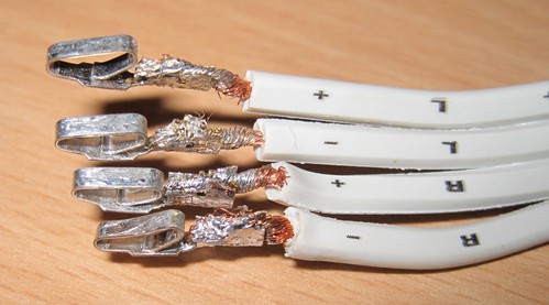
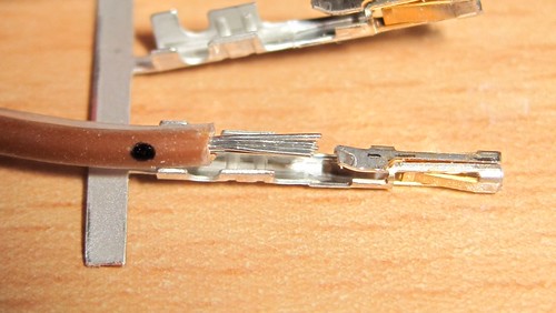
To use this effectively, you need a set of crimp pins, and you need to carefully strip and trim the wire, like this :
Trimmed wire
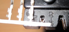
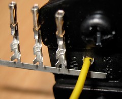
Then you need to insert a crimp pin into the appropriate jaws - note you don't always need to remove them from the strip, I found them easier to handle by bending a single pin away from the strip.
crimp socket inserted
Then, insert the wire : I marked a small dot with a sharpie to mark the appropriate depth:
Ready to crimp
Pull the handles together until they're all crimped - rinse and repeat:
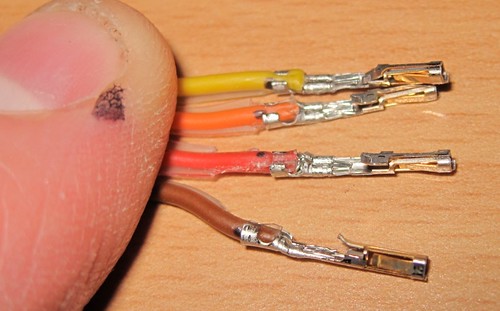
four pins in two minutes
So much easier and more efficient than the manual pliers/solder method. They're not 'perfect' yet - according to the spec I've got a little too much insulation in there - but it's a damn sight neater than my first attempts a couple of years ago :-).
Completed Plug :
Completed plug

Friday 21 October 2011

Greetings fellow b3tans!

Amazing! 3-d printing is now officially mainstream - it's appeared in B3TA!

Thursday 20 October 2011

Crimpin' - my style

I must admit I wasn't that familiar with crimping before starting my RepRap. For the uninitiated, it's the method of attaching the wires to the various plugs to connect to the PCBs. The main connections are the 4-pin stepper motors and the 3-pin headers for the endstops. I also use a 3-pin connector for the thermistor sensor.


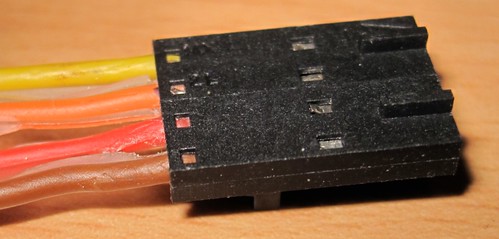
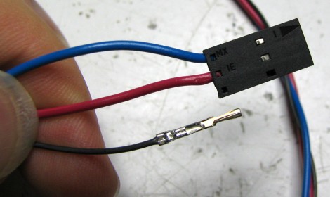
The connector consists of some metal pins with tabs, and the tabs are crimped onto the wires. The metal pins then fit into a plastic housing that makes the plug.
My early attempts involved squishing a bare wire between the tabs with some pliers. However, some of my crimped joints were not well attached: sometimes the pins would deform, so they didn't fit into the housing properly, and often the wire would either fall out, or I'd end up breaking some of the wire strands. I usually ended up squishing and then trying to solder them, often also melting the insulation.
This caused a recent problem where my extruder stepper was not moving - I thought it was due to the firmware, but it was actually a failing stepper connection - two of the wires had bad, intermittent connections.

Using my obsession to understand every part of my 'rap, I did some digging. Mr Nophead had an excellent video which solved my immediate problems :-


Looking a little deeper, there are a multitude of articles on the subject : this article on pinball repair has an excellent overview and good advice. The *key* point seems to be using the proper tools. Using the proper crimping tool makes a good crimp joint easy. The Society of Robots tutorial also has a clear guide, and even our own RepRap forum had a useful discussion.

Time to bite the bullet and get a proper tool. Although you can spend over a hundred pounds on a crimping tool, every manufacturer has a slightly different tool, several different sizes and styles, and most are expensive.
After a bit more research, I found that the 'cheap' (<£15) muti-size crimping tools are only useful for automobile connectors (anything with three coloured dots on it - they are too large),  'bootlace ferrules' crimpers are also not suitable (wrong shape), and the telephone/RJ45 crimping tools are special. The 'molex' and other open crimping terminal styles we use are a lot smaller, typically described using wire gauges, e.g. 22-24AWG of 24-28AWG. However, I did find one reasonably cheap well-reviewed tool - the Multicomp HT225D - available from Rapid(£20) and Farnell(£37). The correct tools have a small 'B' shaped indent, which bends the tabs back on themselves to tightly hold the wire. A properly crimped joint does not need soldering and is more than strong enough for RepRapping connections.

Also worth noting is the huge variety of crimping pins, housings, gold/brass/tin platings, and huge number of options when you go looking to buy connectors. Note that certain pins fit certain housings - you need to make sure the pins, housings, sockets all come from the same range - there are a bewildering array - just see the molex site! The two Molex ranges I found most applicable to RepRapping were the KK range (cheap and cheerful, already used for the stepper and range sensors) and the SL range. Both are available in the 2.54mm (0.1 inch) pitch that the RepRap boards use for the endstops and I use for my steppers.
I personally prefer the SL crimping terminals (16-02-0088)- they look like they will connect better (holding from both sides) rather that the KK terminals that push one side against the housing. I also picked up some 3-way and 4-way housings for the terminals. According to the Molex site, they will use the 70058 range of pins, which include the 16-02-0088.
I went for the gold-plated terminals, as the header pins on my boards are already gold-plated, and the gold-plated terminals have a lifetime of 100 cycles (plugging and unplugging) - the tin ones only have 25 cycles. I also wanted some reasonably chunky wire for the steppers, so I got some 4-way 24AWG ribbon cable, which determined the size of the crimp terminals (22-24AWG) I needed.
I also picked up some male pins (16-02-0081) - so I can make some wire-to-wire connectors. Most of my wires have awful twisted and soldered bodges where they're connected together - covered with heatshrink when I remembered to put it on before soldering, and insulation tape when I didn't. I'd like to replace my bodges with proper pluggable connections, particularly with the stepper wires.

I hope this will fix my dodgy connection issues, and also will tidy my 'rap wiring up at the same time.
:-)

Sunday 4 September 2011

One step forward...

I spent the last couple of days fiddling with software and firmware.
I started with the 'official' RepRap host and firmware, but since I've got a complete mix of electronics (single Arduino mega, self-designed mega shield, separate extruder boards (X,Y, Z, E) and custom heater board), I needed to update all of the pin assignments and configuration files.

I made reasonable progress, managed to get the XYZ axes working fine, but it refused to turn the extruder stepper. I tried various things, ( including heating extruder to 200C), but it refused to move.
I then tried to get the latest host / firmware from git, but while doing this managed to mess up my java3d configuration slightly. Now, all I get is :

DEBUG: Attempting to initialize Arduino/Sanguino [0.174s/87ms]
Exception in thread "J3D-Renderer-1" java.lang.UnsatisfiedLinkError: javax.media.j3d.NativeScreenInfo.openDisplay()J
        at javax.media.j3d.NativeScreenInfo.openDisplay(Native Method)
        at javax.media.j3d.NativeScreenInfo.getStaticDisplay(NativeScreenInfo.java:48)
        at javax.media.j3d.NativeScreenInfo.isGLX13(NativeScreenInfo.java:36)
        at javax.media.j3d.NativeConfigTemplate3D.getBestConfiguration(NativeConfigTemplate3D.java:67) 
... 
I've tracked this down to a missing j3d*.so file. I have tried a number of things (setting LD_LIBRARY_PATH, java.library.path, putting the .so files in the current directory, etc) but there is also a problem with 64/32bit libraries. Downloading latest versions of the libraries, etc also didn't help :-(. I think it is more subtle than just missing the .so file in the path.

I switched to use replicatorG - nice program - but the 5d firmware still didn't move the extruder (after fixing some baud rate problems).

Finally, I updated to the 'Sprinter' firmware - slightly easier to configure - and this, in conjunction with the ultimaker version of replicatorG, allows me to move the extruder stepper!! woohoo!

Now, to test the heater/extruder, configure the parameters, connect up the axes...

Edit:
Oops. Nothing to do with firmware problems, just some dodgy intermittent connections on my stepper. Unplugging the mega during the firmware 'upgrade' wobbled the wire, making it work the next time...
Nothing to do with the firmware versions!!!

Wednesday 31 August 2011

Back on the horse!

After a long delay, I have finally got back to rewrapping!
I dusted off the darwin, tightened the bolts, and rubbed the rust spots off the rails (stored in the garage - not good!). A couple of the acrylic joints had cracked, and a couple of the cross-bracing rods had come off. I tided and reaffixed as best I can. I spent yesterday and today re-plugging the gen2 stepper driver boards into my gen3/Arduino mega setup, and then fixing the firmware for my custom setup.
While uploading the firmware, I was getting a lot of errors -
Binary sketch size: 28098 bytes (of a 126976 byte maximum)

avrdude: stk500_paged_load(): (a) protocol error, expect=0x14, resp=0xa7
avrdude: stk500_cmd(): programmer is out of sync

Although the upload still *seemed* to work, it was a little worrying. Occasionally, it would work OK, but almost every upload would report this error.
Checking the internet, one post mentioned interrupts causing problems. I know that interrupts are used in the firmware for stepper timing and extruder heater control. I found that if I uploaded the 'blink' sketch first (nice, short quick sketch) and then the firmware, it uploads successfully without any errors!
YMMV :-)

Sunday 31 July 2011

Calibre, and Kindle, and books on the Calibre Webserver

Sad but true - I spent my friday night fiddling with PCs.

I've got a Kindle - an excellent reader - and a bunch of ebooks I've downloaded from Gutenberg. I already use Calibre to load the ebooks onto the kindle, but I liked the idea of accessing the library over my wifi network. Calibre has a built-in web server, on port 8080. (Also delete the calibre web username/password, and convert all your books to MOBI or LIT formats).

The Kindle browser is flawed though - it only connects over port 80 (HTTP) or 443 (S) :-(

I already had apache running on my main server (Giles) on port 80, so time for some tweaking:

I set up an alias for my server (in /etc/hosts/) :
127.0.0.1 localhost
127.0.1.1 giles

192.168.0.11 calibre.giles.local

# The following lines are desirable for IPv6 capable hosts
::1     ip6-localhost ip6-loopback
fe00::0 ip6-localnet
ff00::0 ip6-mcastprefix
ff02::1 ip6-allnodes
ff02::2 ip6-allrouters
192.168.0.11 is giles's static IP address. calibre.giles.local is my new virtual server name.

Added an apache conf file to use a virtual host (/etc/apache2/conf.d/calibre.conf):

ProxyPreserveHost On
ProxyPass / http://192.168.0.11:8080/
ProxyPassReverse / http://192.168.0.11:8080/
ServerName calibre.giles.local

This tells apache to route any traffic from calibre.giles.local to the calibre webserver (port 8080).

Now, using a browser on giles, I can see the calibre server by visiting http://calibre.giles.local

This works great, but only when I'm on giles - from any other machine, I would have to edit the 'hosts' file to add the DNS entry - and on the kindle that's not possible.

OK, more tweaking:

Installed dnsmasq (sudo apt-get install dnsmasq). This is a local DNS caching server - it caches the DNS records so it speeds up your browsing (fractionally) but more importantly, it also serves the local /etc/hosts file - so my new calibre.giles.local adress will be served to anyone using this DNS server.
Changed the /etc/resolv.conf:
nameserver 192.168.0.11
i.e. - get giles to use it's own dns server.

Changed /etc/dnsmasq.conf to add :
resolv-file=/etc/resolv2.conf
This avoids dnsmasq using itself to look up entries!

server=194.168.4.100
server=194.168.8.100
These are the two Virgin Media cable DNS servers (my ISP): I could also have used any public DNS servers.

Restarting dnsmasq (service dnsmasq restart) to pick up the changes, I can test this :
dig google.com 
gives me 9ms the first time, the 0ms the second - the cache is working.
dig calibre.giles.local 
shows 0ms - it is in the hosts file.

So, to make my entire network pick up the new DNS server: Login to my Apple Airport router, and go to IP (Internet) settings. Change the DNS list to have 192.168.0.11 first in the list.

All my other machines on the network use the airport router as the DHCP server and gateway/DNS proxy.

So:
Kindle connects to the wireless network - gets the DHCP address and a DNS server of 192.168.0.1 (the AirPort router).
Go to menu - experimental - web browser and type in "calibre.giles.local".
Kindle asks the airport router DNS for the address.
Airport router DNS asks Giles DNSmasq for the address. Found in local hosts file.

Kindle now displays the calibre web interface. You can search for books/authors, download and read any book (click on the MOBI file) :-)

Wednesday 20 July 2011

VNC problems in ubuntu?

I've been using VNC to remote access my two Ubuntu Natty Narwhal machines, and having terrible trouble - the VNC screen not updating, to controlling properly, etc.

It looks like the 3D and special effects play havoc with the VNC server - not displaying properly, etc.

Try using
gdmsetup
- the 'login settings' manager under the administration menu, or go to the top-right switch icon and and click System Settings, then 'Login Screen'.

Enter your admin password, then select 'Ubuntu Classic (No effects)' as the default session. Reboot or logout/login.

This changes ubuntu to use the standard gnome menubar and disables the 3d and animation effects.
I found that VNC worked much better with the classic menu and desktop effects off :-).

Monday 4 July 2011

Multiple webcams on ZoneMinder (Part 4)

Some success!

The USB 3.0 route turns out to be a slight misunderstanding. The key factors involved are :
1) Bandwidth required by each camera, and :
2) Number of USB 2.0 controllers.

It appears that USB 1.1, 2.0, and 3.0 subsystems are basically independent of each other.
A USB 2.0 motherboard has a usb 1.1 and a usb 2.0 controller. The *total* bandwidth for the usb2.0 controller is 480M, and any 2.0 devices share this bandwidth (whichever USB port or hub they are on). USB 1.1 devices similarly share a single 1.1 controller (often labelled a legacy controller).

The usb 3 hub I have seems to have a usb 3.0 hub + a usb 2.0 hub (+ probably a usb 1.1 hub).
Connecting two 2.0 devices (direct, of through the hub) shares the bandwidth of a single 2.0 controller on the USB 3.0 card.

Using the uvcvideo bandwidth quirks mode, I can connect two YUUV webcams to a single usb 2.0 controller - any more fail. This is true whether the port is a standard USB 2.0 hub in a 2.0 motherboard socket, or a USB 3.0 hub in a USB card.

To connect more cameras, add more 2.0 controllers. These can be in a USB 3.0 PCI-e card, or a plain USB 2.0 PCI card, or anything else. Apparently the USB 2.0 controllers included on the usb 3 chips are slightly better as they don't have any other demands on them and only have to deal with the usb 2 traffic.


NOTE : the PS3eye camera has a special 'bayer' mode that uses bandwidth more efficiently - if the driver can handle it. This allows windows users to plug in multiple PS3 eye cameras (see Code Laboratories or iPisoft) I haven't found a similar linux driver yet.

So far, I have been able to display 6 cameras simultaneously -
4 x Cheap USB 2.0 webcams - 640x480 at 25fps - YUYV, PAL
2 x PS3 eye cams - 640x480 at 12fps - YUYV, PAL - some breakup.

I have two cams on a USB 3.0 hub, to a USB 3.0 PCI-E card.
Two cams direct to motherboard controller ports.
Two ps3 eyes on USB 2.0 hub to a USB2.0 PCI controller card.

lsusb -t
davidr@hgwells:~$ lsusb -t
6-1:1.0: No such file or directory
/:  Bus 06.Port 1: Dev 1, Class=root_hub, Driver=xhci_hcd/4p, 5000M
    |__ Port 3: Dev 3, If 0, Class=hub, Driver=hub/4p, 480M
        |__ Port 2: Dev 4, If 0, Class='bInterfaceClass 0x0e not yet handled', Driver=uvcvideo, 480M
        |__ Port 2: Dev 4, If 1, Class='bInterfaceClass 0x0e not yet handled', Driver=uvcvideo, 480M
        |__ Port 4: Dev 5, If 0, Class='bInterfaceClass 0x0e not yet handled', Driver=uvcvideo, 480M
        |__ Port 4: Dev 5, If 1, Class='bInterfaceClass 0x0e not yet handled', Driver=uvcvideo, 480M
/:  Bus 05.Port 1: Dev 1, Class=root_hub, Driver=ohci_hcd/2p, 12M
/:  Bus 04.Port 1: Dev 1, Class=root_hub, Driver=ohci_hcd/3p, 12M
/:  Bus 03.Port 1: Dev 1, Class=root_hub, Driver=ohci_hcd/8p, 12M
/:  Bus 02.Port 1: Dev 1, Class=root_hub, Driver=ehci_hcd/5p, 480M
    |__ Port 4: Dev 2, If 0, Class=vend., Driver=ov534, 480M
    |__ Port 4: Dev 2, If 1, Class=audio, Driver=snd-usb-audio, 480M
    |__ Port 4: Dev 2, If 2, Class=audio, Driver=snd-usb-audio, 480M
    |__ Port 5: Dev 3, If 0, Class=vend., Driver=ov534, 480M
    |__ Port 5: Dev 3, If 1, Class=audio, Driver=snd-usb-audio, 480M
    |__ Port 5: Dev 3, If 2, Class=audio, Driver=snd-usb-audio, 480M
/:  Bus 01.Port 1: Dev 1, Class=root_hub, Driver=ehci_hcd/8p, 480M
    |__ Port 1: Dev 2, If 0, Class=hub, Driver=hub/4p, 480M
        |__ Port 1: Dev 3, If 0, Class='bInterfaceClass 0x0e not yet handled', Driver=uvcvideo, 480M
        |__ Port 1: Dev 3, If 1, Class='bInterfaceClass 0x0e not yet handled', Driver=uvcvideo, 480M
        |__ Port 2: Dev 4, If 0, Class='bInterfaceClass 0x0e not yet handled', Driver=uvcvideo, 480M
        |__ Port 2: Dev 4, If 1, Class='bInterfaceClass 0x0e not yet handled', Driver=uvcvideo, 480M
        |__ Port 4: Dev 5, If 0, Class=hub, Driver=hub/4p, 12M
            |__ Port 1: Dev 6, If 0, Class=HID, Driver=usbhid, 12M
            |__ Port 1: Dev 6, If 1, Class=HID, Driver=usbhid, 12M
            |__ Port 4: Dev 7, If 0, Class=hub, Driver=hub/4p, 12M
                |__ Port 2: Dev 8, If 0, Class=HID, Driver=usbhid, 12M
                |__ Port 2: Dev 8, If 1, Class=HID, Driver=usbhid, 12M
                |__ Port 3: Dev 9, If 0, Class=HID, Driver=wacom, 1.5M
davidr@hgwells:~$ 

Sunday 3 July 2011

Multiple webcams on ZoneMinder (part 3)

Alternative page for ubuntu AMD64 / zoneminder:

Webcam log:

Install zoneminder
davidr@hgwells:~$ sudo apt-get install zoneminder
Follow normal instructions for a zoneminder .deb installation:
sudo ln -s /etc/zm/apache.conf /etc/apache2/conf.d/zoneminder.conf
 sudo apache2ctl restart
 sudo chmod 4755 /usr/bin/zmfix
 zmfix -a
 sudo chown www-data.www-data /usr/share/zoneminder/temp
 sudo vi /etc/sysctl.conf 
Add the following lines at the end of the file:
kernel.shmall = 250000000
kernel.shmmax = 250000000
Pick up shared memory changes:
sudo sysctl -p
kernel.shmall = 250000000
kernel.shmmax = 250000000
I have 4 identical cameras plugged in. The order of video0-video3 may change if other cams, etc are added.
davidr@hgwells:~$ ls /dev/video*
/dev/video0  /dev/video1  /dev/video2  /dev/video3
Rather than use the video0 devices, there is a more fixed set of device links in /dev/v4l/by-id and /dev/v4l/by-path.
NOTE: there is a bug in zoneminder that the device name is limited. For some of my cameras, the by-id or by-path was truncated, and zoneminder couldn't find it.
davidr@hgwells:~$ ls /dev/video*
/dev/video0  /dev/video1  /dev/video2  /dev/video3
davidr@hgwells:~$ ls /dev/v4l/by-path/
pci-0000:03:00.0-usb-0:2.1:1.0-video-index0
pci-0000:03:00.0-usb-0:2.2:1.0-video-index0
pci-0000:03:00.0-usb-0:2.3:1.0-video-index0
pci-0000:03:00.0-usb-0:2.4:1.0-video-index0
So, to get around this problem, define my own paths:
davidr@hgwells:~$ sudo mkdir /cam
davidr@hgwells:~$ sudo chmod 777 /cam
davidr@hgwells:~$ cd /cam
davidr@hgwells:/cam$ ln -s /dev/v4l/by-path/pci-0000\:03\:00.0-usb-0\:2.1\:1.0-video-index0 c1
davidr@hgwells:/cam$ ln -s /dev/v4l/by-path/pci-0000\:03\:00.0-usb-0\:2.2\:1.0-video-index0 c2
davidr@hgwells:/cam$ ln -s /dev/v4l/by-path/pci-0000\:03\:00.0-usb-0\:2.3\:1.0-video-index0 c3
davidr@hgwells:/cam$ ln -s /dev/v4l/by-path/pci-0000\:03\:00.0-usb-0\:2.4\:1.0-video-index0 c4
davidr@hgwells:/cam$ ls
c1  c2  c3  c4
davidr@hgwells:/cam$ 
Use a terminal window with
tail -f /tmp/zmdc.log 
to check for any zoneminder problems.
Open firefox to http:\\hgwells.local\zm to get to the web interface.

Add a new monitor. On the source tab, set the source to:
device : /cam/c1
PAL
YUUV
width:320
height:240

I was able to get two cameras up so far: 3 and 4 fail with dmesg :
[ 159.696321] usb 3-2.4: Not enough bandwidth for altsetting 3
[ 172.716216] usb 3-2.3: Not enough bandwidth for new device state.

Good info on USB in linux

* claim for 5 PS3 eye cameras with one USB3.0 card *

Multiple webcams on ZoneMinder

Part 2:
Continuing the webcam saga (see part 1)

USB 1.1 and USB 2.0
I was incorrect in my earlier post. Modern motherboards usually have two usb controllers: a USB 2.0 controller and a 'legacy' USB 1.1 controller. Devices on each port are automatically switched to the right controller, so the problem of one usb 1 device slowing down the whole usb system does not occur.

I suspect something similar is implemented on most usb hubs - my USB 2.0 hub seems to cope fine with a mix of 1.1 and 2.0 devices.

Due to the wording of the USB 2.0 spec, some USB 1.1 webcams are labelled as USB 2.0 - despite the fact that they only connect at 12Mb (usb1.1). This is the case for two of my older webcams - a Targus and a Creative Live! cam both only connect at 1.1 speeds.

USB 3.0
Although Linux does have support for usb3 cards there is a bug in the current Ubuntu 'Natty Narwhal' kernel that means that USB 3.0 hubs may only be recognised as USB 2.0 hubs - you can see them using
lusub -t
connecting at 480M (usb 2.0).
This post suggested that a later version of the kernel would recognise the usb 3.0 hub properly.
I re-installed with the latest alpha version 11.10 (Oneiric Ocelot) which includes a later kernel. It now recognises the hub as 5000M.

Webcam USB Bandwidth
Some research on webcam USB bandwidth turned up a useful trick. Webcams request a whole load of bandwidth, usually more than they need.
Symptoms were fairly easy to spot: Opening one camera with
xawtv -v 1 -c /dev/video0
and at the same time opening /dev/video1 in another terminal led to
libv4l2: error turning on stream: No space left on device
VIDIOC_STREAMON - Unable to start capture: No space left on device
fps is set to 1/30
libv4l2: error turning on stream: Device or resource busy
VIDIOC_STREAMON - Unable to start capture: Device or resource busy

This post and this post gave me some useful pointers. The uvcvideo kernel module can be set to ignore the requested bandwidth, and to calculate the right bandwidth. Try:
sudo rmmod uvcvideo
sudo modprobe uvcvideo quirks=128
This will be reset every reboot. If this works, create the following file:
sudo vi /etc/modprobe.d/uvcvideo.conf 
containing the line:
options uvcvideo quirks=128

My Hardware setup
My new hardware - in case anyone wants to follow in my footsteps:
Transcend PCI Express Interface USB 3.0 Dual Expansion Card

Tsunami SSU34 100mm USB 3.0 4 Ports Hub

Webcam with Microphone for XP Vista PC Laptop MSN Skype

Output from lsusb :
davidr@hgwells:~$ lsusb -t
/:  Bus 04.Port 1: Dev 1, Class=root_hub, Driver=xhci_hcd/2p, 5000M
    |__ Port 2: Dev 2, If 0, Class=hub, Driver=hub/4p, 5000M
/:  Bus 03.Port 1: Dev 1, Class=root_hub, Driver=xhci_hcd/2p, 480M
    |__ Port 2: Dev 2, If 0, Class=hub, Driver=hub/4p, 480M
        |__ Port 1: Dev 3, If 0, Class='bInterfaceClass 0x0e not yet handled', Driver=uvcvideo, 480M
        |__ Port 1: Dev 3, If 1, Class='bInterfaceClass 0x0e not yet handled', Driver=uvcvideo, 480M
        |__ Port 2: Dev 4, If 0, Class='bInterfaceClass 0x0e not yet handled', Driver=uvcvideo, 480M
        |__ Port 2: Dev 4, If 1, Class='bInterfaceClass 0x0e not yet handled', Driver=uvcvideo, 480M
        |__ Port 3: Dev 5, If 0, Class='bInterfaceClass 0x0e not yet handled', Driver=uvcvideo, 480M
        |__ Port 3: Dev 5, If 1, Class='bInterfaceClass 0x0e not yet handled', Driver=uvcvideo, 480M
        |__ Port 4: Dev 6, If 0, Class='bInterfaceClass 0x0e not yet handled', Driver=uvcvideo, 480M
        |__ Port 4: Dev 6, If 1, Class='bInterfaceClass 0x0e not yet handled', Driver=uvcvideo, 480M
/:  Bus 02.Port 1: Dev 1, Class=root_hub, Driver=ohci_hcd/8p, 12M
/:  Bus 01.Port 1: Dev 1, Class=root_hub, Driver=ehci_hcd/8p, 480M
    |__ Port 1: Dev 2, If 0, Class=hub, Driver=hub/4p, 480M
        |__ Port 4: Dev 3, If 0, Class=hub, Driver=hub/4p, 12M
            |__ Port 1: Dev 4, If 0, Class=HID, Driver=usbhid, 12M
            |__ Port 1: Dev 4, If 1, Class=HID, Driver=usbhid, 12M
            |__ Port 4: Dev 5, If 0, Class=hub, Driver=hub/4p, 12M
                |__ Port 2: Dev 6, If 0, Class=HID, Driver=usbhid, 12M
                |__ Port 2: Dev 6, If 1, Class=HID, Driver=usbhid, 12M
                |__ Port 3: Dev 7, If 0, Class=HID, Driver=wacom, 1.5M
davidr@hgwells:~$ lsusb
Bus 001 Device 001: ID 1d6b:0002 Linux Foundation 2.0 root hub
Bus 002 Device 001: ID 1d6b:0001 Linux Foundation 1.1 root hub
Bus 003 Device 001: ID 1d6b:0002 Linux Foundation 2.0 root hub
Bus 004 Device 001: ID 1d6b:0003 Linux Foundation 3.0 root hub
Bus 001 Device 002: ID 05e3:0608 Genesys Logic, Inc. USB-2.0 4-Port HUB
Bus 003 Device 002: ID 2109:3431  
Bus 004 Device 002: ID 2109:0810  
Bus 001 Device 003: ID 05e3:0604 Genesys Logic, Inc. USB 1.1 Hub
Bus 003 Device 003: ID 090c:937b Feiya Technology Corp. Silicon Motion Camera
Bus 003 Device 004: ID 090c:937b Feiya Technology Corp. Silicon Motion Camera
Bus 003 Device 005: ID 090c:937b Feiya Technology Corp. Silicon Motion Camera
Bus 003 Device 006: ID 090c:937b Feiya Technology Corp. Silicon Motion Camera
Bus 001 Device 004: ID 046d:c049 Logitech, Inc. G5 Laser Mouse
Bus 001 Device 005: ID 05f3:0081 PI Engineering, Inc. Kinesis Integrated Hub
Bus 001 Device 006: ID 05f3:0007 PI Engineering, Inc. Kinesis Advantage PRO MPC/USB Keyboard
Bus 001 Device 007: ID 056a:0013 Wacom Co., Ltd Graphire 3 4x5

Sunday 26 June 2011

Monitoring a 3D Printer

I have tidied my new workshop and I am starting to play with 3d-printing again.

One of the ideas I've been thinking about for some time is remote monitoring of the printing process. Many prints can take several hours to complete and I don't have enough confidence to leave it alone for that long. Jumping up and down to check it every few minutes would quickly get annoying, so I wanted a way to control and monitor it from a web interface.

My plan is to use a few webcams to provide pictures of the bed, print, and overall mechanics, and an emergency stop button. Looking around, the best solution for webcam streaming on Linux (Ubuntu) is ZoneMinder - it can cope with streaming multiple webcams. I used apt-get to install it and there are some extra configuration required in the documentation. I can also point a couple of cameras out the window as a home-made CCTV/security solution.

After a bit of fiddling, I was able to get streaming webcam from my PS3 eye webcam: but the other three webcams refused to stream. This was a little odd, since I could happily get pictures using cheese, kamino, xawtv, and they all seemed to connect properly as /dev/video devices and appeared as v4l2 (VideoForLinux) devices. All drivers seemed OK and installed.
xawtv -c /dev/video0 -v 1 can provide useful information, such as the supported colour palettes.

Checking the zoneminder logs ( appearing in /tmp):
tail -f /tmp/zmdc.log 

24/06/11 22:14:03.046389 zmdc[2171].INF [Starting pending process, zmc -d /dev/video3]
24/06/11 22:14:03.047635 zmdc[2171].INF ['zmc -d /dev/video0' starting at 11/06/24 22:14:03, pid = 2869]
24/06/11 22:14:06.224901 zmdc[2171].ERR ['zmc -d /dev/video0' exited abnormally, exit status 11]
And I was also getting messages in
dmesg
[ 1929.678445] gspca: bandwidth not wide enough - trying again
[ 2529.745525] ohci_hcd 0000:00:0b.0: leak ed ffff880036a43730 (#85) state 2
Checking the USB devices looked OK:
davidr@hgwells:~$ lsusb 
Bus 002 Device 008: ID 046d:c049 Logitech, Inc. G5 Laser Mouse
Bus 002 Device 007: ID 056a:0013 Wacom Co., Ltd Graphire 3 4x5
Bus 002 Device 006: ID 05f3:0007 PI Engineering, Inc. Kinesis Advantage PRO MPC/USB Keyboard
Bus 002 Device 005: ID 0ac8:307b Z-Star Microelectronics Corp. USB 1.1 Webcam
Bus 002 Device 004: ID 05f3:0081 PI Engineering, Inc. Kinesis Integrated Hub
Bus 002 Device 003: ID 093a:2600 Pixart Imaging, Inc. Typhoon Easycam USB 330K (newer)/Typhoon Easycam USB 2.0 VGA 1.3M/Sansun SN-508
Bus 002 Device 002: ID 041e:4053 Creative Technology, Ltd Live! Cam Video IM
Bus 002 Device 001: ID 1d6b:0001 Linux Foundation 1.1 root hub
Bus 001 Device 006: ID 05ac:1293 Apple, Inc. iPod Touch 2.Gen
Bus 001 Device 002: ID 1415:2000 Nam Tai E&E Products Ltd. or OmniVision Technologies, Inc. Sony Playstation Eye
Bus 001 Device 001: ID 1d6b:0002 Linux Foundation 2.0 root hub
davidr@hgwells:~$ 
but checking the USB tree shows that the 3 problem devices are only connecting in USB 1.1 (12M), and the one working device at USB 2.0 (480M).
davidr@hgwells:~$ lsusb -t
1-5:3.0: No such file or directory
/:  Bus 02.Port 1: Dev 1, Class=root_hub, Driver=ohci_hcd/8p, 12M
    |__ Port 2: Dev 2, If 0, Class=vend., Driver=zc3xx, 12M
    |__ Port 4: Dev 4, If 0, Class=hub, Driver=hub/4p, 12M
        |__ Port 2: Dev 6, If 0, Class=HID, Driver=usbhid, 12M
        |__ Port 2: Dev 6, If 1, Class=HID, Driver=usbhid, 12M
        |__ Port 3: Dev 7, If 0, Class=HID, Driver=wacom, 1.5M
        |__ Port 4: Dev 8, If 0, Class=HID, Driver=usbhid, 12M
        |__ Port 4: Dev 8, If 1, Class=HID, Driver=usbhid, 12M
    |__ Port 6: Dev 5, If 0, Class=vend., Driver=zc3xx, 12M
/:  Bus 01.Port 1: Dev 1, Class=root_hub, Driver=ehci_hcd/8p, 480M
    |__ Port 1: Dev 2, If 0, Class=vend., Driver=ov534, 480M
    |__ Port 1: Dev 2, If 1, Class=audio, Driver=snd-usb-audio, 480M
    |__ Port 1: Dev 2, If 2, Class=audio, Driver=snd-usb-audio, 480M
    |__ Port 5: Dev 6, If 0, Class=still, Driver=, 480M
    |__ Port 5: Dev 6, If 1, Class=vend., Driver=usbfs, 480M
Damn. It looks like I forgot the rule about mixing usb 1 and 2 devices - Plugging usb 1 and 2 forces everything on that hub to run as USB 1 (UPDATE : false).

Mixing around the ports, I still had problems. As a better solution, I've ordered a PCI-E USB 3.0 card and usb3 hub. Each port should  happily accept a 2.0 webcam, and should have plenty of bandwidth.
I usually use ebuyer.com, but in this case amazon.co.uk were a lot cheaper! (Usb3.0 card for £10 - hub for £20)

UPDATE:
It seems that the other cameras I had were, in fact, usb1.1 - (even though a couple were labelled as USB 2).  A later experiment with four identical USB 2.0 cameras had similar results.
The main problem does seem to be the USB bandwidth. Apparently cameras 'reserve' USB bandwidth (sometimes more than they use) and the usb 2.0 480Mb limit quickly gets used up. I'll post again after testing with USB3.0 (5Gb)

Thursday 31 March 2011

Andtec Builders Review

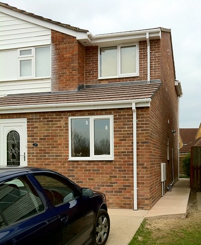
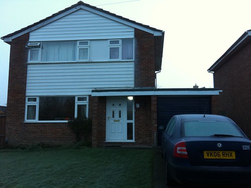
Recently, we have had our house extended. Since there are lots of people complaining about builders on the internet, I thought I would redress the balance by posting a review of a positive experience we've had with Andtec Builders.
After
After
Before
Before

Andy (Owner of Andtec Builders) was recommended to us by a family friend. We had some plans drawn up by an architect, and we got three builders including Andtec to quote.

Andtec quoted the lowest price: but they had several jobs on, and we'd have to wait several months until they were free. One builder was slightly more expensive (within a few percent) but available now: and one quote was significantly over (40% higher).

We decided to wait for Andy based on the recommendations.

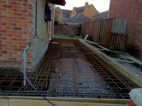
A few weeks before, we met with Andy and talked through the project. Andy had experience with the local area and identified a problem with the foundations specified : our house was built on 'made up' ground and they'd have to dig down a long way to lay the foundations on the 'real' ground level (as specified in the building regs). The original architect was unable to make the changes to the plans but Andy confirmed the problem and found an architect that was able to design a floating raft foundation - a reinforced concrete slab that would do the job.

The original estimate for the work was about 3.5 months : Starting mid november, should have the external walls complete by Xmas, roof on by end Jan, internals done by end Feb.
IMG_0038
The existing garage disappeared very quickly and work on the foundations went well - it was a bit muddy during the excavations but was a lot better once the concrete slab had been poured. Although the work was in front of the door, Andy made sure we had safe access to the house and worked around our many comings and goings :-).

Work on the external walls was delayed a little by extreme weather - during December, we had a very cold snap (-15C at times) and they went to some lengths to keep working - gas heaters, insulation shelters and tarpaulins to try and warm the bricks so that the mortar could set properly without freezing. I know it was cold - we handed out hot tea, and when we collected the mugs a couple of hours later, one was half-full of solid ice! They valiantly worked through the freezing weather - Andy, Jez (the brickie) and George (labourer) only stopped working the week before christmas, where the snow was a few inches deep and couldn't be melted by the salt. In total, several days were lost due to the weather.

January went well - the floors and roofing went on and a few days into February the roofing was done and the scaffolding was coming down. Once the structure was secure, the work knocking through into the main house began.

We had three walls removed, with steel beams inserted, and an extra door through into the hall. This is the most intrusive part of the build : for the first couple of months, most of the work was outside, and didn't really impact on our daily life. My wife is not well, and is at home all the time. Andy went to some effort to try and organise and schedule jobs to minimise the impact on the household, including leaving the kitchen working as long as possible. Luckily, the new kitchen was in part of the new extension, so Andy was able to put in the new kitchen before ripping out the old one, making the transition much easier than it otherwise might be.
This part of the build also went well - although it's inevitably a bit dusty :-).
Finishing
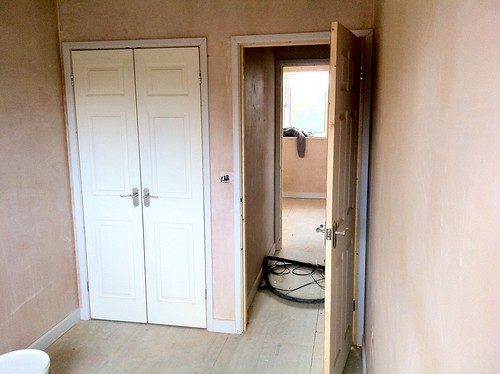
Plastering and finishing was good - we asked Andy to do several extra jobs, which he quoted for and added to the scheduled monthly bills. We asked him to plaster the old kitchen ceiling and replace several internal doors, and to lay a wooden floor throughout the downstairs.

All in all, we were very pleased with Andtec builders and their work. Andy and all the staff were polite and professional at all times, and Andy was always happy to discuss and answer questions about any part of the work.

The estimates and scheduling of the job was excellent : Despite the slippage due to the weather, the work was completed according to the early schedule. The additions to the work (installing a new kitchen, flooring, and extra internal work) all went according to estimates.

Professionalism was excellent : They turned up at 8am every day and worked until 4pm. When they were unable to work (due to the snow) we were informed by phone. Because there was a lot of work, if a particular job could not be done (for example due to tiles not arriving) they continued with other work and rescheduled around problems. Someone else commented that they were very tidy - although it was a building site (literally) it was organised well.
All building regulations, inspections, and certificates (gas, electric work, etc) were all present and correct. Estimates, contracts, changes to the contracts and scheduled bills were printed and very clear and supplied on time, so we always knew what was asked for and how much it would cost.

Andy was polite and helpful at all times. Several times specific decisions had to be made (Front door style, positions of sockets, tiles) and Andy gave us options and time to allow considered decisions before ordering or installing.
Badger (badge)
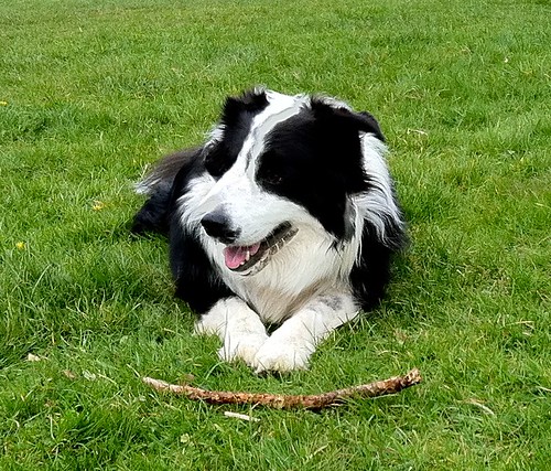
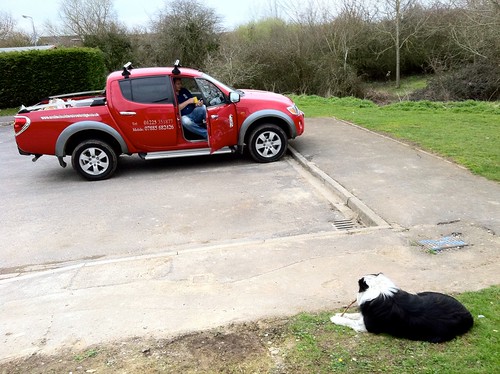
Along with the building crew, Andy often brought 'Badge' with him. Badger is a lovely border collie, well trained, smart and very friendly. Badge was quite at ease with all the heavy machinery, and would only come in when invited, and didn't jump up or bother anyone - very well behaved. He even made friends with one of our cats (the other two kept well away!).

I would happily recommend AndTec builders to anyone in or around Bath, Frome and Trowbridge.
IMG_0164
Thanks, Andy.

Lots of photos of the build in-progress on my flickr feed.