I managed to break my original BfB extruder :-(. The acrylic had flexed too many times, and the top retaining bracket broke in half. The screw thread now carefully unscrews itself rather than driving the filament down :-(
So, time to update to a modern wade-style or similar extruder, using a hobbled bolt. Of course, I could have bought the gear drives from the many RepRap shops or ebay, but that's too easy :-).
Instead, I found an old cheap hand drill, with similar sized gearing. It turned out to be on an 8mm shaft.
I added a 5mm to 8mm sleeve to a stepper motor (made from a sex bolt) and drilled and tapped a 4mm hole for a grub screw - I could then attach the smaller gear to the stepper shaft. The larger gear I cut a small square indent to match a carriage bolt, and cut some teeth into the threads using a dremmel cutting disc. A plastic cutting board and an Ikea bracket made a mount, and three skate bearings (8mm 908) made up a channel for the filament.
It's not pretty, and it's heavier than ABS gearing, but it grips the filament like anything - I can't stop it using my full strength grip, and really forces the filament through.
I'm currently building a heater block and nozzle to add on the bottom. Hopefully this 'RepStrapStruder' will last long enough for me to print a proper wade's extruder.
My new Mega boards arrived - all good.
Simple tests worked fine, but after uploading the RepRap host software at 115200 Baud, had problems connecting and even uploading new sketches. I had to press reset and upload almost straightaway, otherwise the upload failed.
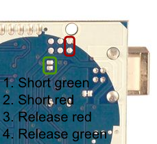
A bit of research suggested an updated Atmega 8u2 firmware (the usb chip). (also the new boards appear as /dev/ttyASM0 instead of /dev/ttyUSB0 - update to the latest RXTX libraries.
Borrowed from a forum post by stimmer on this thread
I saw that a new Uno firmware had been uploaded to the Arduino repository. I've been trying it out, it seems pretty good so far, tools menu and serial monitor are much more reliable and it only failed to program once. (Although the Duemilanove was never perfect either)
I have managed to blow my Arduino mega board.
It stopped uploading, and there was a 'hot' smell - never a good sign. Unplugging everything, the arduino chip was very hot indeed.
After waiting for it to cool, I found that plugging it into the USB socket - nothing else - started to make the mega chip warm up, and it got too hot to touch. :-(
Another circuit board is sacrificed to the gods of knowledge and experience.
Tracing things back, I wondered how it happened. My setup hadn't changed, I'd just been running heater and extruder tests - the steppers weren't plugged in, so it was unlikely to be them.
Looking at the my heater board again, I realised that the output pin of the arduino was connected straight to ground through the MOSFET gate - no current limiting resistor. A bit of digging uncovered a possible problem - the design I'd used as a base (RepRap Gen 2/3) had the same circuit, but used current limiting Mosfets. I'd upgraded mine to larger ones, but checking the data sheet, the Mosfet gate acts a bit like a capacitor. Charging the gate could be done slow(with a resistor) or fast. A current of 2A was given as an example to charge the gate in 14nS.
Oh. The arduino pins can only handle 100mA or so. Still, it only does that when it's switched on or off, so long as I wasn't switching it on and off thousands of times a second - like using PWM.... Damn.
Looking back, it's surprising that it coped as well as it did - it should have gone up in smoke straightaway! I'm impressed it worked at all - it coped for several hours of testing. Each time it switched, the arduino pin was directly connected to ground - drawing a big current for a few mS, then when it switched off, the mosfet gate would discharge itself straight through the arduinio pin to ground.
I have now redesigned my heater / Mosfet board to incorporate a 560ohm current limiting resistor (between the arduino pin and the mosfet gate), and also a pull-down 100k resistor between the Mosfet gate and ground. It should limit the current to 90mA, and make sure the gates switch off if the board isn't connected.
I've also ordered a couple of new Ardunios - hopefully I'll be more careful with these...
:-)
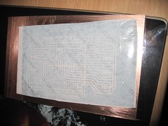
I've been using the laser toner method for a while to make my PCBs. It seems to work well for me, I print out the PCBs using a Samsung ML2010 laser printer, tape them to a cleaned copper board, then run them through a laminator twice. The heat fuses the toner to the board, and as long as your paper isn't too sticky, you can peel it straight off and etch.
I've been using this successfully, even for larger boards like my Arduino mega shield. The key variable seems to be the paper. I have the best results by cutting a square of sticker backing paper, using the stickers to stick it to the centre of a normal sheet of paper, then printing the PCB from Eagle. This works well, but I do need a sheet of stickers (like the A4 laser printing stickers) every time.
Other people have reported success with tracing paper, or magazine paper. I grabbed some tracing paper (two types, Goldline 63gsm and Goldline 112gsm) paper and gave it a try. It printed well, but didn't stick too well - you need to soak the paper to remove it, and most of my toner came off with the paper. Maybe my laminator wasn't hot enough :-(.
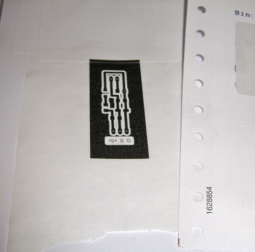
So, I'd run out of labels, my tracing paper experiments weren't working well - and then my eye fell on a discarded Farnell packing bill on my table. The Farnell packing receipts are printed on some sort of fan-fold sticker paper so that the address labels can be removed and stuck to the box. The whole bill is basically one big sticker! I cut a square, stuck it to a sheet of paper using the sticker I'd just removed, and ran it through the printer.
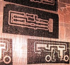
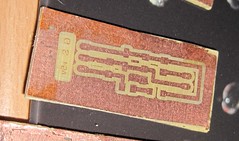
Perfect result, first time! The toner transferred very well to the board:
The finished board (a SMT version of the tiny thermistor circuit) looks great and from the detail (on the lettering) this would work with much finer traces!
I'll start saving up all my old shipping receipts instead of buying printer labels now....
P.S. top tip - after the stickers have been 'laminated' and cooled, if you gently rub the back of the sticker with your thumb, a small 'bubble' forms that gently lifts the sticker backing away from the toner bit by bit. I get almost 100% adhesion with this technique.
After a few days, my new crimping toys tools arrived in the post.
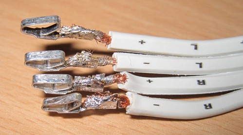
Here's a joint from a couple of years BC (Before Crimptool) :
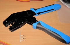
However, that was before the RVFM HT-225D, which I got from Rapid.
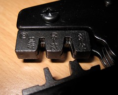
It has the correct 'B' shaped jaws to make proper crimp joints:
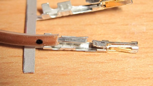
To use this effectively, you need a set of crimp pins, and you need to carefully strip and trim the wire, like this :
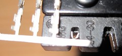
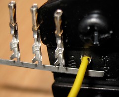
Then you need to insert a crimp pin into the appropriate jaws - note you don't always need to remove them from the strip, I found them easier to handle by bending a single pin away from the strip.
Then, insert the wire : I marked a small dot with a sharpie to mark the appropriate depth:
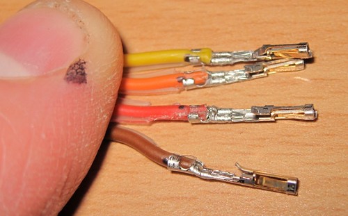
Pull the handles together until they're all crimped - rinse and repeat:
So much easier and more efficient than the manual pliers/solder method. They're not 'perfect' yet - according to the spec I've got a little too much insulation in there - but it's a damn sight neater than my first attempts a couple of years ago :-).
Completed Plug :
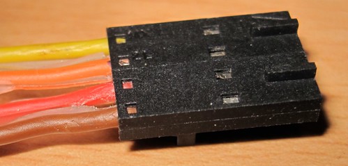
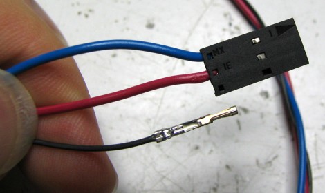
I must admit I wasn't that familiar with crimping before starting my RepRap. For the uninitiated, it's the method of attaching the wires to the various plugs to connect to the PCBs. The main connections are the 4-pin stepper motors and the 3-pin headers for the endstops. I also use a 3-pin connector for the thermistor sensor.
The connector consists of some metal pins with tabs, and the tabs are crimped onto the wires. The metal pins then fit into a plastic housing that makes the plug.
My early attempts involved squishing a bare wire between the tabs with some pliers. However, some of my crimped joints were not well attached: sometimes the pins would deform, so they didn't fit into the housing properly, and often the wire would either fall out, or I'd end up breaking some of the wire strands. I usually ended up squishing and then trying to solder them, often also melting the insulation.
This caused a recent problem where my extruder stepper was not moving - I thought it was due to the firmware, but it was actually a failing stepper connection - two of the wires had bad, intermittent connections.
Using my obsession to understand every part of my 'rap, I did some digging. Mr Nophead had an excellent video which solved my immediate problems :-
Time to bite the bullet and get a proper tool. Although you can spend over a hundred pounds on a crimping tool, every manufacturer has a slightly different tool, several different sizes and styles, and most are expensive.
After a bit more research, I found that the 'cheap' (<£15) muti-size crimping tools are only useful for automobile connectors (anything with three coloured dots on it - they are too large), 'bootlace ferrules' crimpers are also not suitable (wrong shape), and the telephone/RJ45 crimping tools are special. The 'molex' and other open crimping terminal styles we use are a lot smaller, typically described using wire gauges, e.g. 22-24AWG of 24-28AWG. However, I did find one reasonably cheap well-reviewed tool - the Multicomp HT225D - available from Rapid(£20) and Farnell(£37). The correct tools have a small 'B' shaped indent, which bends the tabs back on themselves to tightly hold the wire. A properly crimped joint does not need soldering and is more than strong enough for RepRapping connections.
Also worth noting is the huge variety of crimping pins, housings, gold/brass/tin platings, and huge number of options when you go looking to buy connectors. Note that certain pins fit certain housings - you need to make sure the pins, housings, sockets all come from the same range - there are a bewildering array - just see the molex site! The two Molex ranges I found most applicable to RepRapping were the KK range (cheap and cheerful, already used for the stepper and range sensors) and the SL range. Both are available in the 2.54mm (0.1 inch) pitch that the RepRap boards use for the endstops and I use for my steppers.
I personally prefer the SL crimping terminals (16-02-0088)- they look like they will connect better (holding from both sides) rather that the KK terminals that push one side against the housing. I also picked up some 3-way and 4-way housings for the terminals. According to the Molex site, they will use the 70058 range of pins, which include the 16-02-0088.
I went for the gold-plated terminals, as the header pins on my boards are already gold-plated, and the gold-plated terminals have a lifetime of 100 cycles (plugging and unplugging) - the tin ones only have 25 cycles. I also wanted some reasonably chunky wire for the steppers, so I got some 4-way 24AWG ribbon cable, which determined the size of the crimp terminals (22-24AWG) I needed.
I also picked up some male pins (16-02-0081) - so I can make some wire-to-wire connectors. Most of my wires have awful twisted and soldered bodges where they're connected together - covered with heatshrink when I remembered to put it on before soldering, and insulation tape when I didn't. I'd like to replace my bodges with proper pluggable connections, particularly with the stepper wires.
I hope this will fix my dodgy connection issues, and also will tidy my 'rap wiring up at the same time.
:-)