Sunday, 28 March 2010

Recycled Heated Bed

I finally put together an idea that I've had floating around for a while.
My wife had an old heated pad where the fabric had worn through. I took out the plug and element, and saved it, because I though it probably had some nichrome wire in the element.
Fast forward several months, to all this recent talk of headed beds.
I uncovered the element from my 'parts' box, and inspected it - the insulation is all intact, all well covered, no damage and safe. A careful test showed it still warmed up when plugged in.
I grabbed a couple of steel baking trays from Wilkinsons (£1 each) and my kapton tape.
From HeatedBed
I punched a hole in one of the trays, carefully bending the edges and masking them with tape so there were no sharp edges. I could then feed the element through and taped it to the back of the tray in a rough spiral with the kapton tape.
From HeatedBed
The other tray, I covered the base with strips of kapton tape, and placed over the element tray. VERY IMPORTANT: I added an earth wire grounding both of the trays to mains earth (the PSU case).
From HeatedBed
Hey presto, heated bed.

Firing it up, it reached 80C+ in a couple of minutes on 'full'. I haven't run it further than that without mounting it properly first.

Potential problems:
  • Using Mains electricity - you need to be *very* careful and earth the case. Check your safety three times.
  • I don't know what temperature it will reach: it needs to be mounted properly and tested. Temperature control is provided by the original power box - I can have 1, 2, or 3 and it will automatically switch off after 90 mins. (probably not a problem unless I'm doing a long print).
  • The surfaces of the tins are relatively thin pressed steel. I suspect they're flat enough for 'small' prints (up to makerbot size) - I'll have to see if they're flat/rigid enough for larger objects.
Potential improvements:
  • I could fill the thin gap between the element and the two plates with fire cement: it might improve heat conduction and possible help with stiffness/flatness.

Monday, 22 March 2010

SMD - it ain't so hard!

I soldered my first surface mount board successfully! It was a lot easier than I expected...
I thought I'd write up my novice guide to SMD soldering, so any other novices have the confidence to get started.

Step 1 - get organised
I found a beading box from the local market stitching/craft stall had plenty of small boxes for my smd components. I labelled the blank strips as I took them out of the labelled bags, marking the component values several times along their length, because if they get mixed up the numbers are too small to read without a magnifying glass. Sort out and safely store the components. I marked each box with the value and the component number (R3, C4, etc) using post-its.
From SMD_stepper
Clean and scrub the circuit boards, so the copper is perfectly clean and ready to accept the solder. I used a trusty green scourer and Cif cleaner(light abrasive).
I also used the laserprinter method to print the silkscreen layer to make it easier to place the components.
From SMD_stepper

Step 2 - Working space and tools

Sort out a working space. I used several sheets of A4 paper taped together, because components show up well against them.
From SMD_stepper
While placing, I needed some kitchen/loo roll to wipe the solder paste off tools. I also used:
From SMD_stepper
Solder paste, a couple of pairs of tweezers (the curved point ones are best), and a sharp knife. Printout a large copy of the PCB diagram with the component layout, and a separate list of the component values and numbers. It's much easier to double check before you solder, not after.
From SMD_stepper
A magnifying glass is essential. Luckily, my wife had a nice big glass on a flexible mount for her cross-stich, so I could borrow that.

Step 3 - Solder paste
Add a tiny amount of solder paste to each pad. I went with the absolute minimum, thinking it wuould be easier to add more later than remove it - but it was more than enough. I ended up using the point of the tweezers and the point of the knife to move extra paste from pad to pad. For the IC, I spread a line of paste all along the pins, and then used the blade to split each individual pads apart, cutting a gap between individual pads.

Step 4 - Place Components
Gently peel apart the film from the carrier, and tap the components onto the paper. Using the tweezers, place the components onto the pasted pads. Check and double-check the values or labels, and check the diagram to make sure of the positioning. Getting perfect alignment is not essential, but make sure the electrical contacts will be correct.

Step 5 - Apply heat
Lots of internet advice talks about temperature controlled ovens, customized hotplates, etc. I haven't got any of that, so I whacked it on my electric cooker ring.
From SMD_stepper

I'm not recommending this, although it worked for me (although I seem to have cooked a couple of green LEDs). The solder paste starts off a murky grey but when the solder hits temperature, it suddenly becomes a nice shiny solder joint and pulls the components into place.
I put the board on a cold cooker ring, turned it to 6 (full) and watched it. Once the joints popped, I quickly checked them (one corner was slightly raised, pressing it down with the tweezers popped the last few joints) and when they were all done, turned it off. After it had cooled enough to touch, I moved it and let it cool completely.

Inspection photos:
From SMD_stepper

Step 6 - Remaining through-hole components
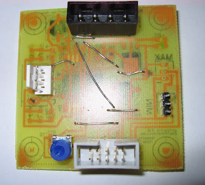
I soldered the remaining through-hole components (mainly connectors) and added some wire bridges, because I only have a single sided board. This is also why the SMD components are on the bottom and the through-hole are on top.
From SMD_stepper
A couple of the green LEDs don't work, and the 4-pin connectors I have are the wrong size, and the 10-pin IDC connector has ended up reversed, but I wired it up to an arduino and a NEMA-17 stepper and it runs the stepper fine. All in all, a good experiment.

I'll fix the board and run off a few more for my Mendel - I've got enough components for four more stepper boards. Single-sided eagle files are available and are based on the stepper driver 2.3 from MakerBot.

Thursday, 18 March 2010

UK Suppliers

Recently, I've come across a couple of parts that might be useful to UK RepRappers.

I found a stepper driver board from DIY CNC

It's based on the A3977 stepper driver chip, like the version 3 of the RepRap stepper driver board. It has handy dipswitches to select down to 1/8 stepping, and handles up to 2.5 amps. There are screw terminals for the connections and an optional edge connector. Although the recommended voltage is 24v+, I've contacted the chap, and he says it should work down to 10v - and the board design seems pretty similar to the 12v RepRap boards. One board is £27 but there's a discount for buying 3 or 4 for a Mendel. Certainly worth a look as an alternative to a polulu-type board imported from the states, if MakerBot is out of stock.

I've just finished building a single-sided SMD version of the 2.3 stepper driver, and I've got the parts for a few more, so I haven't tried these personally.

On the other hand, I did buy an Arduino mega for £25 from D-Robotics from an Ebay auction. Arrived after a couple of days, seems to be a 'clone' of the reference design from a hong kong/chinese company.
From SMD_stepper

Plugged in, recognized as an arduino mega, example sketch loaded straight off.

Should be a good upgrade from my Gen2 (arduino) electronics: I should be able to load in the 5D firmware, unplug my breakout shield from the arduino and plug in the Mega!

Tuesday, 16 March 2010

Arduino Mega Shield

I'm fiddling with an eagle design for a RepRap arduino mega shield. I couldn't find any eagle files for the basic sheild pins, so here's one I ripped from the arduino reference design.

Arduino Mega Shield Eagle Files

Sunday, 28 February 2010

Schoolboy Error

In my last two boards, I made a schoolboy error:
Both boards (due to different reasons) ended up being reversed left-to-right.
Now, during the transfer from paper to the board, it does mirror/reverse the image. I had 'overcompensated' and flipped the board twice, i.e. the wrong way.

Also, the stepper driver experiment was for the brand new 3.0 version, not the tried and tested 2.3 version (as noticed in the comments).

I've knocked together a version of a single sided board for the stepper driver v2.3 here - you want the v2 for the 2.3 board (eagle and .brd files provided). I dropped the ethernet connections (too many holes) and reverted back to the RepRap 3-pin connectors for the max/min endstops.

Here's a couple of etched boards, using the laserprinter/laminator/dab etching method:
From PCB
From PCB
I had to tidy a couple of edge tracks with a CD pen, but they came out well.

Here's my temperature controller (0-100 degrees C, controlling a relay) for another project:

From PCB
I bought some more copper board today from Maplins, so I should be able to make them a bit larger next time and avoid the issues with the transfer at the edge of the board.
Now to drilling several hundred holes with my new dremmel...

Saturday, 20 February 2010

Etched boards

Here's the two boards I etched using the laserprinter/laminator method.

From PCB


From PCB


The laminator bound the laser toner to the boards really well. I used a few mm of ferric chloride, and dabbed/rubbed it onto the board with a cotton wool ball (wearing GLOVES). The centre etched first, and I was able to rub more around the edges to finish off the etch.

The etching worked really well. The detail came out fantastically - even the drill marks came out on the stepper board. You can also clearly see a minature mouse pointer in the centre of the temperature board - oops!

The toner bound so well to the copper that I had to scrub the completed boards with a green scourer and cif to get the toner off - it was harder work than cleaning the boards in the first place!
There is a small error on the stepper board (bottom left corner, just above the resistors). When transferring the laserprint to the board, before the laminator, I accidentally smudged a track. This is probably repairable when I add the via/wire bridges.

[Edit - I thought this was based on the Makerbot stepper driver (A3982) - but I actually picked up the files from the RepRap distribution, which are actually V3.0 of the stepper driver, based on the A3977. Wow, I'm ahead of the curve!]
Schematic:
From PCB

Friday, 19 February 2010

Ah! That's the way to do it!

Last night, I got round to making a couple of PCBs with the LaserPrinter method, using a couple of tips scavenged off the comments and interweb.
From PCB
I printed onto some sticker backing paper from some laserprinter address labels I had around. The first sheet, which was completely sticker-free, was a bit thin and bendy and got jammed up in the rollers and didn't print properly. After retrieving the sheet (and extracting a cat toy from the inside of my LaserPrinter), I removed a few stickers from the centre of a new sheet of stickers, so it was thicker and stiffer.
This printed perfectly.

I then taped on my cleaned copper board (Cif and green scourer again) and put it through a cheap home laminator machine.

This worked really really well. The toner transferred perfectly to the copper, and the sticker paper was left completely clean. It seems to have bonded well to the copper, so I will have a go at etching the boards soon.
From PCB
I re-printed my temperature controller PCB board. Since I only had a PDF of the circuit diagram, I had to mirror it before printing. Last time, I used a command-line utility and a converter - but this converted the tracks into a low-res jpg, which worked but was certainly not the best quality.
This time, I printed out the PDF version and measured the printed PCB (49mm). I then zoomed in, so the tracks were filling the whole screen (in the PDF reader) and took a screenshot. This screenshot can be cropped to the edge marks, and flipped in GIMP, and GIMP offers specific print options to print out at exact sizes - i.e. the size measured earlier. This worked well (apart from a minature mouse pointer appearing on my PCB tracks!)

Single Sided Makerbot Stepper Driver board
From PCB
I've been trying to get hold of the Stepper driver board for a little while, but while waiting I thought I'd try and make a single-sided version of the PCB that was easier to etch at home.
First task was getting to grips with Eagle, and downloading the .brd files from the RepRap repository. The biggest problem with the mix of through hole and surface mount components is that the pads end up on both sides of the board - the through hole pads are on the bottom, and surface mount on the top.
I loaded up Eagle and mirrored the through hole components onto the other side of the board. The plugs are now pointing downwards (not ideal) but at least the pads are now on the top side. Rotating the connectors by 180 degrees helped match the tracks to the existing routes.
This left lots of messy tracks on the board, but a bit of work tidied them up. I then went to work moving via's (that would now have to be wire links) and moving the via points so they are not underneath the surface mount components, as I'd have to through-hole solder them. I'm no circuit board designer, so I went with moving the components as little as possible, and re-routed the tracks to avoid or shorten the vias where I could. Straightening the vias helped avoid crossing wires, and some of the connectors could be connected directly.

I printed off the PCB and transferred it to the copper. If it etches well, and I can drill some holes without ripping all of the tiny tracks off the board, it might be worth getting some components to build up a version.

[Edit - here are the eagle board files for anyone who's interested. Probably there will be later versions that might actually work.]