I soldered my first surface mount board successfully! It was a lot easier than I expected...
I thought I'd write up my novice guide to SMD soldering, so any other novices have the confidence to get started.
Step 1 - get organisedI found a beading box from the local market stitching/craft stall had plenty of small boxes for my smd components. I labelled the blank strips as I took them out of the labelled bags, marking the component values several times along their length, because if they get mixed up the numbers are too small to read without a magnifying glass. Sort out and safely store the components. I marked each box with the value and the component number (R3, C4, etc) using post-its.
Clean and scrub the circuit boards, so the copper is perfectly clean and ready to accept the solder. I used a trusty green scourer and Cif cleaner(light abrasive).
I also used the laserprinter method to print the silkscreen layer to make it easier to place the components.
Step 2 - Working space and toolsSort out a working space. I used several sheets of A4 paper taped together, because components show up well against them.
While placing, I needed some kitchen/loo roll to wipe the solder paste off tools. I also used:
Solder paste, a couple of pairs of tweezers (the curved point ones are best), and a sharp knife. Printout a large copy of the PCB diagram with the component layout, and a separate list of the component values and numbers. It's much easier to double check before you solder, not after.
A magnifying glass is essential. Luckily, my wife had a nice big glass on a flexible mount for her cross-stich, so I could borrow that.
Step 3 - Solder pasteAdd a tiny amount of solder paste to each pad. I went with the absolute minimum, thinking it wuould be easier to add more later than remove it - but it was more than enough. I ended up using the point of the tweezers and the point of the knife to move extra paste from pad to pad. For the IC, I spread a line of paste all along the pins, and then used the blade to split each individual pads apart, cutting a gap between individual pads.
Step 4 - Place Components Gently peel apart the film from the carrier, and tap the components onto the paper. Using the tweezers, place the components onto the pasted pads. Check and double-check the values or labels, and check the diagram to make sure of the positioning. Getting perfect alignment is not essential, but make sure the electrical contacts will be correct.
Step 5 - Apply heat Lots of internet advice talks about temperature controlled ovens, customized hotplates, etc. I haven't got any of that, so I whacked it on my electric cooker ring.
I'm not recommending this, although it worked for me (although I seem to have cooked a couple of green LEDs). The solder paste starts off a murky grey but when the solder hits temperature, it suddenly becomes a nice shiny solder joint and pulls the components into place.
I put the board on a cold cooker ring, turned it to 6 (full) and watched it. Once the joints popped, I quickly checked them (one corner was slightly raised, pressing it down with the tweezers popped the last few joints) and when they were all done, turned it off. After it had cooled enough to touch, I moved it and let it cool completely.
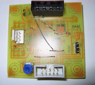
Inspection photos:
Step 6 - Remaining through-hole components I soldered the remaining through-hole components (mainly connectors) and added some wire bridges, because I only have a single sided board. This is also why the SMD components are on the bottom and the through-hole are on top.
A couple of the green LEDs don't work, and the 4-pin connectors I have are the wrong size, and the 10-pin IDC connector has ended up reversed, but I wired it up to an arduino and a NEMA-17 stepper and it runs the stepper fine. All in all, a good experiment.
I'll fix the board and run off a few more for my Mendel - I've got enough components for four more stepper boards.
Single-sided eagle files are available and are based on the stepper driver 2.3 from MakerBot.