I have managed to blow my Arduino mega board.
It stopped uploading, and there was a 'hot' smell - never a good sign. Unplugging everything, the arduino chip was very hot indeed.
After waiting for it to cool, I found that plugging it into the USB socket - nothing else - started to make the mega chip warm up, and it got too hot to touch. :-(
Another circuit board is sacrificed to the gods of knowledge and experience.
Tracing things back, I wondered how it happened. My setup hadn't changed, I'd just been running heater and extruder tests - the steppers weren't plugged in, so it was unlikely to be them.
Looking at the my heater board again, I realised that the output pin of the arduino was connected straight to ground through the MOSFET gate - no current limiting resistor. A bit of digging uncovered a possible problem - the design I'd used as a base (RepRap Gen 2/3) had the same circuit, but used current limiting Mosfets. I'd upgraded mine to larger ones, but checking the data sheet, the Mosfet gate acts a bit like a capacitor. Charging the gate could be done slow(with a resistor) or fast. A current of 2A was given as an example to charge the gate in 14nS.
Oh. The arduino pins can only handle 100mA or so. Still, it only does that when it's switched on or off, so long as I wasn't switching it on and off thousands of times a second - like using PWM.... Damn.
Looking back, it's surprising that it coped as well as it did - it should have gone up in smoke straightaway! I'm impressed it worked at all - it coped for several hours of testing. Each time it switched, the arduino pin was directly connected to ground - drawing a big current for a few mS, then when it switched off, the mosfet gate would discharge itself straight through the arduinio pin to ground.
I have now redesigned my heater / Mosfet board to incorporate a 560ohm current limiting resistor (between the arduino pin and the mosfet gate), and also a pull-down 100k resistor between the Mosfet gate and ground. It should limit the current to 90mA, and make sure the gates switch off if the board isn't connected.
I've also ordered a couple of new Ardunios - hopefully I'll be more careful with these...
:-)
Showing posts with label reprap. Show all posts
Showing posts with label reprap. Show all posts
Tuesday, 1 November 2011

Sunday, 30 October 2011
Recycling!
I've been using the laser toner method for a while to make my PCBs. It seems to work well for me, I print out the PCBs using a Samsung ML2010 laser printer, tape them to a cleaned copper board, then run them through a laminator twice. The heat fuses the toner to the board, and as long as your paper isn't too sticky, you can peel it straight off and etch.

I've been using this successfully, even for larger boards like my Arduino mega shield. The key variable seems to be the paper. I have the best results by cutting a square of sticker backing paper, using the stickers to stick it to the centre of a normal sheet of paper, then printing the PCB from Eagle. This works well, but I do need a sheet of stickers (like the A4 laser printing stickers) every time.
Other people have reported success with tracing paper, or magazine paper. I grabbed some tracing paper (two types, Goldline 63gsm and Goldline 112gsm) paper and gave it a try. It printed well, but didn't stick too well - you need to soak the paper to remove it, and most of my toner came off with the paper. Maybe my laminator wasn't hot enough :-(.
So, I'd run out of labels, my tracing paper experiments weren't working well - and then my eye fell on a discarded Farnell packing bill on my table. The Farnell packing receipts are printed on some sort of fan-fold sticker paper so that the address labels can be removed and stuck to the box. The whole bill is basically one big sticker! I cut a square, stuck it to a sheet of paper using the sticker I'd just removed, and ran it through the printer.

Perfect result, first time! The toner transferred very well to the board:


The finished board (a SMT version of the tiny thermistor circuit) looks great and from the detail (on the lettering) this would work with much finer traces!
I'll start saving up all my old shipping receipts instead of buying printer labels now....
P.S. top tip - after the stickers have been 'laminated' and cooled, if you gently rub the back of the sticker with your thumb, a small 'bubble' forms that gently lifts the sticker backing away from the toner bit by bit. I get almost 100% adhesion with this technique.
I've been using this successfully, even for larger boards like my Arduino mega shield. The key variable seems to be the paper. I have the best results by cutting a square of sticker backing paper, using the stickers to stick it to the centre of a normal sheet of paper, then printing the PCB from Eagle. This works well, but I do need a sheet of stickers (like the A4 laser printing stickers) every time.
Other people have reported success with tracing paper, or magazine paper. I grabbed some tracing paper (two types, Goldline 63gsm and Goldline 112gsm) paper and gave it a try. It printed well, but didn't stick too well - you need to soak the paper to remove it, and most of my toner came off with the paper. Maybe my laminator wasn't hot enough :-(.
So, I'd run out of labels, my tracing paper experiments weren't working well - and then my eye fell on a discarded Farnell packing bill on my table. The Farnell packing receipts are printed on some sort of fan-fold sticker paper so that the address labels can be removed and stuck to the box. The whole bill is basically one big sticker! I cut a square, stuck it to a sheet of paper using the sticker I'd just removed, and ran it through the printer.
Perfect result, first time! The toner transferred very well to the board:
The finished board (a SMT version of the tiny thermistor circuit) looks great and from the detail (on the lettering) this would work with much finer traces!
I'll start saving up all my old shipping receipts instead of buying printer labels now....
P.S. top tip - after the stickers have been 'laminated' and cooled, if you gently rub the back of the sticker with your thumb, a small 'bubble' forms that gently lifts the sticker backing away from the toner bit by bit. I get almost 100% adhesion with this technique.
Crimptastic!
After a few days, my new crimping toys tools arrived in the post.
Here's a joint from a couple of years BC (Before Crimptool) :

However, that was before the RVFM HT-225D, which I got from Rapid.

It has the correct 'B' shaped jaws to make proper crimp joints:

To use this effectively, you need a set of crimp pins, and you need to carefully strip and trim the wire, like this :

Then you need to insert a crimp pin into the appropriate jaws - note you don't always need to remove them from the strip, I found them easier to handle by bending a single pin away from the strip.

Then, insert the wire : I marked a small dot with a sharpie to mark the appropriate depth:

Pull the handles together until they're all crimped - rinse and repeat:

So much easier and more efficient than the manual pliers/solder method. They're not 'perfect' yet - according to the spec I've got a little too much insulation in there - but it's a damn sight neater than my first attempts a couple of years ago :-).
Completed Plug :

However, that was before the RVFM HT-225D, which I got from Rapid.
It has the correct 'B' shaped jaws to make proper crimp joints:
To use this effectively, you need a set of crimp pins, and you need to carefully strip and trim the wire, like this :
Then you need to insert a crimp pin into the appropriate jaws - note you don't always need to remove them from the strip, I found them easier to handle by bending a single pin away from the strip.
Then, insert the wire : I marked a small dot with a sharpie to mark the appropriate depth:
Pull the handles together until they're all crimped - rinse and repeat:
So much easier and more efficient than the manual pliers/solder method. They're not 'perfect' yet - according to the spec I've got a little too much insulation in there - but it's a damn sight neater than my first attempts a couple of years ago :-).
Completed Plug :
Thursday, 20 October 2011
Crimpin' - my style
I must admit I wasn't that familiar with crimping before starting my RepRap. For the uninitiated, it's the method of attaching the wires to the various plugs to connect to the PCBs. The main connections are the 4-pin stepper motors and the 3-pin headers for the endstops. I also use a 3-pin connector for the thermistor sensor.


The connector consists of some metal pins with tabs, and the tabs are crimped onto the wires. The metal pins then fit into a plastic housing that makes the plug.
My early attempts involved squishing a bare wire between the tabs with some pliers. However, some of my crimped joints were not well attached: sometimes the pins would deform, so they didn't fit into the housing properly, and often the wire would either fall out, or I'd end up breaking some of the wire strands. I usually ended up squishing and then trying to solder them, often also melting the insulation.
This caused a recent problem where my extruder stepper was not moving - I thought it was due to the firmware, but it was actually a failing stepper connection - two of the wires had bad, intermittent connections.
Using my obsession to understand every part of my 'rap, I did some digging. Mr Nophead had an excellent video which solved my immediate problems :-
Looking a little deeper, there are a multitude of articles on the subject : this article on pinball repair has an excellent overview and good advice. The *key* point seems to be using the proper tools. Using the proper crimping tool makes a good crimp joint easy. The Society of Robots tutorial also has a clear guide, and even our own RepRap forum had a useful discussion.
Time to bite the bullet and get a proper tool. Although you can spend over a hundred pounds on a crimping tool, every manufacturer has a slightly different tool, several different sizes and styles, and most are expensive.
After a bit more research, I found that the 'cheap' (<£15) muti-size crimping tools are only useful for automobile connectors (anything with three coloured dots on it - they are too large), 'bootlace ferrules' crimpers are also not suitable (wrong shape), and the telephone/RJ45 crimping tools are special. The 'molex' and other open crimping terminal styles we use are a lot smaller, typically described using wire gauges, e.g. 22-24AWG of 24-28AWG. However, I did find one reasonably cheap well-reviewed tool - the Multicomp HT225D - available from Rapid(£20) and Farnell(£37). The correct tools have a small 'B' shaped indent, which bends the tabs back on themselves to tightly hold the wire. A properly crimped joint does not need soldering and is more than strong enough for RepRapping connections.
Also worth noting is the huge variety of crimping pins, housings, gold/brass/tin platings, and huge number of options when you go looking to buy connectors. Note that certain pins fit certain housings - you need to make sure the pins, housings, sockets all come from the same range - there are a bewildering array - just see the molex site! The two Molex ranges I found most applicable to RepRapping were the KK range (cheap and cheerful, already used for the stepper and range sensors) and the SL range. Both are available in the 2.54mm (0.1 inch) pitch that the RepRap boards use for the endstops and I use for my steppers.
I personally prefer the SL crimping terminals (16-02-0088)- they look like they will connect better (holding from both sides) rather that the KK terminals that push one side against the housing. I also picked up some 3-way and 4-way housings for the terminals. According to the Molex site, they will use the 70058 range of pins, which include the 16-02-0088.
I went for the gold-plated terminals, as the header pins on my boards are already gold-plated, and the gold-plated terminals have a lifetime of 100 cycles (plugging and unplugging) - the tin ones only have 25 cycles. I also wanted some reasonably chunky wire for the steppers, so I got some 4-way 24AWG ribbon cable, which determined the size of the crimp terminals (22-24AWG) I needed.
I also picked up some male pins (16-02-0081) - so I can make some wire-to-wire connectors. Most of my wires have awful twisted and soldered bodges where they're connected together - covered with heatshrink when I remembered to put it on before soldering, and insulation tape when I didn't. I'd like to replace my bodges with proper pluggable connections, particularly with the stepper wires.
I hope this will fix my dodgy connection issues, and also will tidy my 'rap wiring up at the same time.
:-)
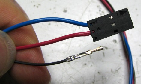

My early attempts involved squishing a bare wire between the tabs with some pliers. However, some of my crimped joints were not well attached: sometimes the pins would deform, so they didn't fit into the housing properly, and often the wire would either fall out, or I'd end up breaking some of the wire strands. I usually ended up squishing and then trying to solder them, often also melting the insulation.
This caused a recent problem where my extruder stepper was not moving - I thought it was due to the firmware, but it was actually a failing stepper connection - two of the wires had bad, intermittent connections.
Using my obsession to understand every part of my 'rap, I did some digging. Mr Nophead had an excellent video which solved my immediate problems :-
Looking a little deeper, there are a multitude of articles on the subject : this article on pinball repair has an excellent overview and good advice. The *key* point seems to be using the proper tools. Using the proper crimping tool makes a good crimp joint easy. The Society of Robots tutorial also has a clear guide, and even our own RepRap forum had a useful discussion.
Time to bite the bullet and get a proper tool. Although you can spend over a hundred pounds on a crimping tool, every manufacturer has a slightly different tool, several different sizes and styles, and most are expensive.
After a bit more research, I found that the 'cheap' (<£15) muti-size crimping tools are only useful for automobile connectors (anything with three coloured dots on it - they are too large), 'bootlace ferrules' crimpers are also not suitable (wrong shape), and the telephone/RJ45 crimping tools are special. The 'molex' and other open crimping terminal styles we use are a lot smaller, typically described using wire gauges, e.g. 22-24AWG of 24-28AWG. However, I did find one reasonably cheap well-reviewed tool - the Multicomp HT225D - available from Rapid(£20) and Farnell(£37). The correct tools have a small 'B' shaped indent, which bends the tabs back on themselves to tightly hold the wire. A properly crimped joint does not need soldering and is more than strong enough for RepRapping connections.
Also worth noting is the huge variety of crimping pins, housings, gold/brass/tin platings, and huge number of options when you go looking to buy connectors. Note that certain pins fit certain housings - you need to make sure the pins, housings, sockets all come from the same range - there are a bewildering array - just see the molex site! The two Molex ranges I found most applicable to RepRapping were the KK range (cheap and cheerful, already used for the stepper and range sensors) and the SL range. Both are available in the 2.54mm (0.1 inch) pitch that the RepRap boards use for the endstops and I use for my steppers.
I personally prefer the SL crimping terminals (16-02-0088)- they look like they will connect better (holding from both sides) rather that the KK terminals that push one side against the housing. I also picked up some 3-way and 4-way housings for the terminals. According to the Molex site, they will use the 70058 range of pins, which include the 16-02-0088.
I went for the gold-plated terminals, as the header pins on my boards are already gold-plated, and the gold-plated terminals have a lifetime of 100 cycles (plugging and unplugging) - the tin ones only have 25 cycles. I also wanted some reasonably chunky wire for the steppers, so I got some 4-way 24AWG ribbon cable, which determined the size of the crimp terminals (22-24AWG) I needed.
I also picked up some male pins (16-02-0081) - so I can make some wire-to-wire connectors. Most of my wires have awful twisted and soldered bodges where they're connected together - covered with heatshrink when I remembered to put it on before soldering, and insulation tape when I didn't. I'd like to replace my bodges with proper pluggable connections, particularly with the stepper wires.
I hope this will fix my dodgy connection issues, and also will tidy my 'rap wiring up at the same time.
:-)
Sunday, 4 September 2011
One step forward...
I spent the last couple of days fiddling with software and firmware.
I started with the 'official' RepRap host and firmware, but since I've got a complete mix of electronics (single Arduino mega, self-designed mega shield, separate extruder boards (X,Y, Z, E) and custom heater board), I needed to update all of the pin assignments and configuration files.
I made reasonable progress, managed to get the XYZ axes working fine, but it refused to turn the extruder stepper. I tried various things, ( including heating extruder to 200C), but it refused to move.
I then tried to get the latest host / firmware from git, but while doing this managed to mess up my java3d configuration slightly. Now, all I get is :
I switched to use replicatorG - nice program - but the 5d firmware still didn't move the extruder (after fixing some baud rate problems).
Finally, I updated to the 'Sprinter' firmware - slightly easier to configure - and this, in conjunction with the ultimaker version of replicatorG, allows me to move the extruder stepper!! woohoo!
Now, to test the heater/extruder, configure the parameters, connect up the axes...
Edit:
Oops. Nothing to do with firmware problems, just some dodgy intermittent connections on my stepper. Unplugging the mega during the firmware 'upgrade' wobbled the wire, making it work the next time...
Nothing to do with the firmware versions!!!
I started with the 'official' RepRap host and firmware, but since I've got a complete mix of electronics (single Arduino mega, self-designed mega shield, separate extruder boards (X,Y, Z, E) and custom heater board), I needed to update all of the pin assignments and configuration files.
I made reasonable progress, managed to get the XYZ axes working fine, but it refused to turn the extruder stepper. I tried various things, ( including heating extruder to 200C), but it refused to move.
I then tried to get the latest host / firmware from git, but while doing this managed to mess up my java3d configuration slightly. Now, all I get is :
DEBUG: Attempting to initialize Arduino/Sanguino [0.174s/87ms]
Exception in thread "J3D-Renderer-1" java.lang.UnsatisfiedLinkError: javax.media.j3d.NativeScreenInfo.openDisplay()J
        at javax.media.j3d.NativeScreenInfo.openDisplay(Native Method)
        at javax.media.j3d.NativeScreenInfo.getStaticDisplay(NativeScreenInfo.java:48)
        at javax.media.j3d.NativeScreenInfo.isGLX13(NativeScreenInfo.java:36)
        at javax.media.j3d.NativeConfigTemplate3D.getBestConfiguration(NativeConfigTemplate3D.java:67)
...I've tracked this down to a missing j3d*.so file. I have tried a number of things (setting LD_LIBRARY_PATH, java.library.path, putting the .so files in the current directory, etc) but there is also a problem with 64/32bit libraries. Downloading latest versions of the libraries, etc also didn't help :-(. I think it is more subtle than just missing the .so file in the path.
I switched to use replicatorG - nice program - but the 5d firmware still didn't move the extruder (after fixing some baud rate problems).
Finally, I updated to the 'Sprinter' firmware - slightly easier to configure - and this, in conjunction with the ultimaker version of replicatorG, allows me to move the extruder stepper!! woohoo!
Now, to test the heater/extruder, configure the parameters, connect up the axes...
Edit:
Oops. Nothing to do with firmware problems, just some dodgy intermittent connections on my stepper. Unplugging the mega during the firmware 'upgrade' wobbled the wire, making it work the next time...
Nothing to do with the firmware versions!!!
Tuesday, 13 July 2010
Sentries report bearings to the south west. Thousands of them.
Well, 53 to be exact.

I've been looking around to collect Mendel parts for a little while, intending to reproduce from my BfB Darwin. I've picked up four nema17 steppers, built myself some stepper drivers and electronics, and I'm now looking for the mechanical parts. On the parts lists are a significant number of bearings, which can be quite pricey.
Luckily, I found RepRapKit.com, based in the UK, and ordered myself a complete set of bearings for less than 20 quid - much cheaper than everywhere else I've looked so far. Excellent service - I had a couple of emails with him and he seems like a really nice friendly chap. Parts were ordered and dispatched quickly, and delivered next day. I got 51 smaller bearings and two M8/skate bearings (including enough to make a geared/stepper extruder), they all look good and turn well. The store is selling ABS and bearings so far, and is looking to expand into extruders and other RepRap bits.
I also got round to blowing the dust off my BfB Darwin. It needs several bolts tightening and some general maintenance, and I disassembled the three stepper motors, covered them in plastic bags and tape, and ground out some proper flattened shafts using my dremmel. Note : metal filings from filing or grinding are not good inside a precision engineered bearing, and since they're highly magnetic, it does tend to attract the dust.

Make sure the bearings and motors are nicely covered (with blutack/tape/plastic bags) otherwise the dirty bearings will seize or grind away very quickly.
I'd had a go at filing the shafts back during the initial assembly, but didn't have the right tools - I did have a few problems with the axes slipping at times. Once it's all back together, it should be fine this time.

I've been looking around to collect Mendel parts for a little while, intending to reproduce from my BfB Darwin. I've picked up four nema17 steppers, built myself some stepper drivers and electronics, and I'm now looking for the mechanical parts. On the parts lists are a significant number of bearings, which can be quite pricey.
Luckily, I found RepRapKit.com, based in the UK, and ordered myself a complete set of bearings for less than 20 quid - much cheaper than everywhere else I've looked so far. Excellent service - I had a couple of emails with him and he seems like a really nice friendly chap. Parts were ordered and dispatched quickly, and delivered next day. I got 51 smaller bearings and two M8/skate bearings (including enough to make a geared/stepper extruder), they all look good and turn well. The store is selling ABS and bearings so far, and is looking to expand into extruders and other RepRap bits.
I also got round to blowing the dust off my BfB Darwin. It needs several bolts tightening and some general maintenance, and I disassembled the three stepper motors, covered them in plastic bags and tape, and ground out some proper flattened shafts using my dremmel. Note : metal filings from filing or grinding are not good inside a precision engineered bearing, and since they're highly magnetic, it does tend to attract the dust.

Make sure the bearings and motors are nicely covered (with blutack/tape/plastic bags) otherwise the dirty bearings will seize or grind away very quickly.
I'd had a go at filing the shafts back during the initial assembly, but didn't have the right tools - I did have a few problems with the axes slipping at times. Once it's all back together, it should be fine this time.
Friday, 25 June 2010
Heater board complete
I've completed and soldered my heater board.

There are 8 PWM outputs from my reprap shield which are boosted using 54A MOSFETS. These should happily drive my extruder heater, heated bed, fans, extra motors, whatever.
I've posted the files to thingiverse. I've also added my single-sided stepper driver files to a thing as well.
I now have four working stepper drivers, one mega shield, and a completed heater PWM board. Only a couple of thermistor sensors, and I'll have a complete set of electronics for a mendel :-)
There are 8 PWM outputs from my reprap shield which are boosted using 54A MOSFETS. These should happily drive my extruder heater, heated bed, fans, extra motors, whatever.
I've posted the files to thingiverse. I've also added my single-sided stepper driver files to a thing as well.
I now have four working stepper drivers, one mega shield, and a completed heater PWM board. Only a couple of thermistor sensors, and I'll have a complete set of electronics for a mendel :-)
Saturday, 19 June 2010
RepRap host software on Mac
Just a quick note to anyone trying to get the RepRap host software to run on a new Mac (Mac OSX 10.6.3).
The librxtxSerial.jnilib file supplied in the reprap software didn't seem to work. I found one at
http://iharder.sourceforge.net/current/java/ and I replaced it with this newer one.
type 'java org.reprap.Main'
This brings up the main reprap windows on my mac, and I was able to load and slice a .stl file. YMMV :-)
Doh!
This is usually true of any other command-line program, but any arguments AFTER the classname are passed to the class Main() method. I blame late-night programming :-)
Ignore all the java/extension rubbish, just use instructions from
http://tonybuser.com/reprap-host-on-osx-snow-leopard
A command line that also works is
I downloaded the software from the wiki and unzipped it.
To get it to work, I had some problems trying to make it accept a classpath. Eventually I did the following:
Make a directory ~/Library/Java/Extensions
Copy any files with *.jar and *.jnilib extensions to that directory.
The librxtxSerial.jnilib file supplied in the reprap software didn't seem to work. I found one at
http://iharder.sourceforge.net/current/java/ and I replaced it with this newer one.
Go to the reprap host software directory in a terminal window (you need to be in a directory with the rr-logo-green-url.png file in it).
type 'java org.reprap.Main'
This brings up the main reprap windows on my mac, and I was able to load and slice a .stl file. YMMV :-)
UPDATE:
As pointed out by Tony, this is not the most elegant solution. It doesn't help that I was looking at the 'mac-experimental' version from last year, rather that re-building from source :-( oops.
As pointed out by Tony, this is not the most elegant solution. It doesn't help that I was looking at the 'mac-experimental' version from last year, rather that re-building from source :-( oops.
I also found out why I was having problems with the classpath :
java org.reprap.Main -cp $CLASSPATHis NOT equivalent to
java -cp $CLASSPATH org.reprap.Main
Doh!
This is usually true of any other command-line program, but any arguments AFTER the classname are passed to the class Main() method. I blame late-night programming :-)
Ignore all the java/extension rubbish, just use instructions from
http://tonybuser.com/reprap-host-on-osx-snow-leopard
A command line that also works is
java -cp "*" org.reprap.Main
Wednesday, 9 June 2010
First Thingiverse submission!
Rather than try and re-create thingiverse manually , I posted my RepRap Mega Shield to Thingiverse.
Enjoy!
Friday, 4 June 2010
Renoir's Mega Shield built
I've been soldering and building and I've finished my mega shield!
The build went well. I 'tinned' the copper pads (using some plumbing flux and a tiny bit of solder), which made the soldering a bit easier. Using a tip (from ladyada?) I converted some standard header pins to some through-pins by pushing them through using the flat on a pair of pliers, three or 4 at a time:
Once I'd fixed the pins, I could put them through into the arduino and check the alignment - OK. I left the pins partially pushed in to maintain the position, and soldered a single pin from each row:
This held them in place when I removed the mega and soldered the rest.
I've now got 10-pin IDC headers for X,Y,Z, and extruder (A) - and a spare (B) using header pins as I ran out of sockets. There's a space for the 20-pin interface connector from the generation 4 designs, and a whole set of +5v/GND/analog in headers for temperature probes, extra sensors, etc. Along the top is an I2C 4-pin header, and similar +5v/GND/digital I/O headers for servos, TX/RX comms, and some PWM pins. 8 PWM outputs are taken to a separate 10-pin IDC header that is intended to go to a MOSFET power driver board to drive the heater and heated bed (coming soon).
 |
| From RenoirsMegaShield |
 |
| From RenoirsMegaShield |
 |
| From RenoirsMegaShield |
 |
| From RenoirsMegaShield |
Monday, 31 May 2010
Mega RepRap sheild
I've been working for a couple of weeks on a RepRap Arduino Mega shield. I've got a mix of early generation 2 electronics, a few home-made single sided generation 3 stepper boards, and old arduino with a screw-terminal shield and a brand-new arduino mega.
I designed myself a version of an arduino mega shield to connect the gen3 stepper boards using the 10-pin IDC cables, and it might be useful for anyone transitioning between generations of electronics. Headlines:
Eagle files for Renoir's RepRap Mega Shield
I've just etched one using my laserprinter/laminator method, and I've just etched two more single-sided stepper drivers. I'll post some photos once it's been assembled.
p.s. All files (and anything on this blog) available under creative commons attribution 3.0 licence.
:-)
I designed myself a version of an arduino mega shield to connect the gen3 stepper boards using the 10-pin IDC cables, and it might be useful for anyone transitioning between generations of electronics. Headlines:
- Single-sided for home-made boards
- 5 stepper driver headers - x,y,z,a,b - should match existing gen3 electronics.
- (future-proof?) UI interface header that *should* match gen4 electronics.
- Heater 10-pin IDC (to plug in MOSFET driver board later) - should be able to drive a reprap setup with 1 or 2 extruders/ heated bed without an additional extruder board.
- I2c header as per standard boards
- Optional extra 3-pin headers for digital in\out and analog in : +5v, GND, and data pin. This makes it easy to add temperature sensors, kill switches, extra limit switches, etc (I'm only using the min endstops).
Eagle files for Renoir's RepRap Mega Shield
I've just etched one using my laserprinter/laminator method, and I've just etched two more single-sided stepper drivers. I'll post some photos once it's been assembled.
p.s. All files (and anything on this blog) available under creative commons attribution 3.0 licence.
:-)
Monday, 17 May 2010
Useful PCB notes
http://www.electricstuff.co.uk/pcbs.html
Nice clear semi-pro PCB instructions :-)
Useful suggestions for PCB-making services
Nice clear semi-pro PCB instructions :-)
Useful suggestions for PCB-making services
Tuesday, 4 May 2010
Mendel home-made stepper boards
A productive weekend: I used the laserprinter technique to make four more single-sided stepper drivers.
I experimented with plain paper, baking paper, greaseproof paper, oiled paper, but the best transfers were with my cheap label backing paper.
To economise on the amount of label paper, I cut a section roughly a bit larger than the PCB, and stuck it to a clean A4 sheet with some of the discarded stickers. This then goes through the laserprinter.
I then took off this section, bent it over the PCB and taped it down, then ran it through my laminator a couple of times. This transferred the toner to the PCB.
After etching, I had four new stepper boards to build
I experimented with plain paper, baking paper, greaseproof paper, oiled paper, but the best transfers were with my cheap label backing paper.
To economise on the amount of label paper, I cut a section roughly a bit larger than the PCB, and stuck it to a clean A4 sheet with some of the discarded stickers. This then goes through the laserprinter.
 |
| From StepperPCBs |
I then took off this section, bent it over the PCB and taped it down, then ran it through my laminator a couple of times. This transferred the toner to the PCB.
 |
| From StepperPCBs |
After etching, I had four new stepper boards to build
 |
| From StepperPCBs |
Sunday, 28 March 2010
Recycled Heated Bed
I finally put together an idea that I've had floating around for a while.
My wife had an old heated pad where the fabric had worn through. I took out the plug and element, and saved it, because I though it probably had some nichrome wire in the element.
Fast forward several months, to all this recent talk of headed beds.
I uncovered the element from my 'parts' box, and inspected it - the insulation is all intact, all well covered, no damage and safe. A careful test showed it still warmed up when plugged in.
I grabbed a couple of steel baking trays from Wilkinsons (£1 each) and my kapton tape.
I punched a hole in one of the trays, carefully bending the edges and masking them with tape so there were no sharp edges. I could then feed the element through and taped it to the back of the tray in a rough spiral with the kapton tape.
The other tray, I covered the base with strips of kapton tape, and placed over the element tray. VERY IMPORTANT: I added an earth wire grounding both of the trays to mains earth (the PSU case).
Hey presto, heated bed.
Firing it up, it reached 80C+ in a couple of minutes on 'full'. I haven't run it further than that without mounting it properly first.
Potential problems:
My wife had an old heated pad where the fabric had worn through. I took out the plug and element, and saved it, because I though it probably had some nichrome wire in the element.
Fast forward several months, to all this recent talk of headed beds.
I uncovered the element from my 'parts' box, and inspected it - the insulation is all intact, all well covered, no damage and safe. A careful test showed it still warmed up when plugged in.
I grabbed a couple of steel baking trays from Wilkinsons (£1 each) and my kapton tape.
 |
| From HeatedBed |
 |
| From HeatedBed |
 |
| From HeatedBed |
Firing it up, it reached 80C+ in a couple of minutes on 'full'. I haven't run it further than that without mounting it properly first.
Potential problems:
- Using Mains electricity - you need to be *very* careful and earth the case. Check your safety three times.
- I don't know what temperature it will reach: it needs to be mounted properly and tested. Temperature control is provided by the original power box - I can have 1, 2, or 3 and it will automatically switch off after 90 mins. (probably not a problem unless I'm doing a long print).
- The surfaces of the tins are relatively thin pressed steel. I suspect they're flat enough for 'small' prints (up to makerbot size) - I'll have to see if they're flat/rigid enough for larger objects.
- I could fill the thin gap between the element and the two plates with fire cement: it might improve heat conduction and possible help with stiffness/flatness.
Monday, 22 March 2010
SMD - it ain't so hard!
I soldered my first surface mount board successfully! It was a lot easier than I expected...
I thought I'd write up my novice guide to SMD soldering, so any other novices have the confidence to get started.
Step 1 - get organised
I found a beading box from the local market stitching/craft stall had plenty of small boxes for my smd components. I labelled the blank strips as I took them out of the labelled bags, marking the component values several times along their length, because if they get mixed up the numbers are too small to read without a magnifying glass. Sort out and safely store the components. I marked each box with the value and the component number (R3, C4, etc) using post-its.
Clean and scrub the circuit boards, so the copper is perfectly clean and ready to accept the solder. I used a trusty green scourer and Cif cleaner(light abrasive).
I also used the laserprinter method to print the silkscreen layer to make it easier to place the components.
Step 2 - Working space and tools
Sort out a working space. I used several sheets of A4 paper taped together, because components show up well against them.
While placing, I needed some kitchen/loo roll to wipe the solder paste off tools. I also used:
Solder paste, a couple of pairs of tweezers (the curved point ones are best), and a sharp knife. Printout a large copy of the PCB diagram with the component layout, and a separate list of the component values and numbers. It's much easier to double check before you solder, not after.
A magnifying glass is essential. Luckily, my wife had a nice big glass on a flexible mount for her cross-stich, so I could borrow that.
Step 3 - Solder paste
Add a tiny amount of solder paste to each pad. I went with the absolute minimum, thinking it wuould be easier to add more later than remove it - but it was more than enough. I ended up using the point of the tweezers and the point of the knife to move extra paste from pad to pad. For the IC, I spread a line of paste all along the pins, and then used the blade to split each individual pads apart, cutting a gap between individual pads.
Step 4 - Place Components
Gently peel apart the film from the carrier, and tap the components onto the paper. Using the tweezers, place the components onto the pasted pads. Check and double-check the values or labels, and check the diagram to make sure of the positioning. Getting perfect alignment is not essential, but make sure the electrical contacts will be correct.
Step 5 - Apply heat
Lots of internet advice talks about temperature controlled ovens, customized hotplates, etc. I haven't got any of that, so I whacked it on my electric cooker ring.
I'm not recommending this, although it worked for me (although I seem to have cooked a couple of green LEDs). The solder paste starts off a murky grey but when the solder hits temperature, it suddenly becomes a nice shiny solder joint and pulls the components into place.
I put the board on a cold cooker ring, turned it to 6 (full) and watched it. Once the joints popped, I quickly checked them (one corner was slightly raised, pressing it down with the tweezers popped the last few joints) and when they were all done, turned it off. After it had cooled enough to touch, I moved it and let it cool completely.
Inspection photos:
Step 6 - Remaining through-hole components
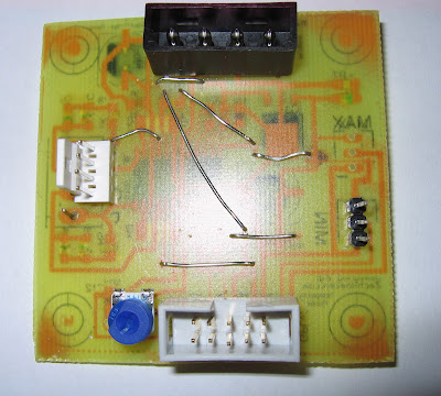
I soldered the remaining through-hole components (mainly connectors) and added some wire bridges, because I only have a single sided board. This is also why the SMD components are on the bottom and the through-hole are on top.
A couple of the green LEDs don't work, and the 4-pin connectors I have are the wrong size, and the 10-pin IDC connector has ended up reversed, but I wired it up to an arduino and a NEMA-17 stepper and it runs the stepper fine. All in all, a good experiment.
I'll fix the board and run off a few more for my Mendel - I've got enough components for four more stepper boards. Single-sided eagle files are available and are based on the stepper driver 2.3 from MakerBot.
I thought I'd write up my novice guide to SMD soldering, so any other novices have the confidence to get started.
Step 1 - get organised
I found a beading box from the local market stitching/craft stall had plenty of small boxes for my smd components. I labelled the blank strips as I took them out of the labelled bags, marking the component values several times along their length, because if they get mixed up the numbers are too small to read without a magnifying glass. Sort out and safely store the components. I marked each box with the value and the component number (R3, C4, etc) using post-its.
 |
| From SMD_stepper |
I also used the laserprinter method to print the silkscreen layer to make it easier to place the components.
 |
| From SMD_stepper |
Step 2 - Working space and tools
Sort out a working space. I used several sheets of A4 paper taped together, because components show up well against them.
 |
| From SMD_stepper |
 |
| From SMD_stepper |
 |
| From SMD_stepper |
Step 3 - Solder paste
Add a tiny amount of solder paste to each pad. I went with the absolute minimum, thinking it wuould be easier to add more later than remove it - but it was more than enough. I ended up using the point of the tweezers and the point of the knife to move extra paste from pad to pad. For the IC, I spread a line of paste all along the pins, and then used the blade to split each individual pads apart, cutting a gap between individual pads.
Step 4 - Place Components
Gently peel apart the film from the carrier, and tap the components onto the paper. Using the tweezers, place the components onto the pasted pads. Check and double-check the values or labels, and check the diagram to make sure of the positioning. Getting perfect alignment is not essential, but make sure the electrical contacts will be correct.
Step 5 - Apply heat
Lots of internet advice talks about temperature controlled ovens, customized hotplates, etc. I haven't got any of that, so I whacked it on my electric cooker ring.
 |
| From SMD_stepper |
I'm not recommending this, although it worked for me (although I seem to have cooked a couple of green LEDs). The solder paste starts off a murky grey but when the solder hits temperature, it suddenly becomes a nice shiny solder joint and pulls the components into place.
I put the board on a cold cooker ring, turned it to 6 (full) and watched it. Once the joints popped, I quickly checked them (one corner was slightly raised, pressing it down with the tweezers popped the last few joints) and when they were all done, turned it off. After it had cooled enough to touch, I moved it and let it cool completely.
Inspection photos:
 |
| From SMD_stepper |
Step 6 - Remaining through-hole components
I soldered the remaining through-hole components (mainly connectors) and added some wire bridges, because I only have a single sided board. This is also why the SMD components are on the bottom and the through-hole are on top.
 |
| From SMD_stepper |
I'll fix the board and run off a few more for my Mendel - I've got enough components for four more stepper boards. Single-sided eagle files are available and are based on the stepper driver 2.3 from MakerBot.
Thursday, 18 March 2010
UK Suppliers
Recently, I've come across a couple of parts that might be useful to UK RepRappers.
I found a stepper driver board from DIY CNC

It's based on the A3977 stepper driver chip, like the version 3 of the RepRap stepper driver board. It has handy dipswitches to select down to 1/8 stepping, and handles up to 2.5 amps. There are screw terminals for the connections and an optional edge connector. Although the recommended voltage is 24v+, I've contacted the chap, and he says it should work down to 10v - and the board design seems pretty similar to the 12v RepRap boards. One board is £27 but there's a discount for buying 3 or 4 for a Mendel. Certainly worth a look as an alternative to a polulu-type board imported from the states, if MakerBot is out of stock.
I've just finished building a single-sided SMD version of the 2.3 stepper driver, and I've got the parts for a few more, so I haven't tried these personally.
On the other hand, I did buy an Arduino mega for £25 from D-Robotics from an Ebay auction. Arrived after a couple of days, seems to be a 'clone' of the reference design from a hong kong/chinese company.
Plugged in, recognized as an arduino mega, example sketch loaded straight off.
Should be a good upgrade from my Gen2 (arduino) electronics: I should be able to load in the 5D firmware, unplug my breakout shield from the arduino and plug in the Mega!
I found a stepper driver board from DIY CNC
It's based on the A3977 stepper driver chip, like the version 3 of the RepRap stepper driver board. It has handy dipswitches to select down to 1/8 stepping, and handles up to 2.5 amps. There are screw terminals for the connections and an optional edge connector. Although the recommended voltage is 24v+, I've contacted the chap, and he says it should work down to 10v - and the board design seems pretty similar to the 12v RepRap boards. One board is £27 but there's a discount for buying 3 or 4 for a Mendel. Certainly worth a look as an alternative to a polulu-type board imported from the states, if MakerBot is out of stock.
I've just finished building a single-sided SMD version of the 2.3 stepper driver, and I've got the parts for a few more, so I haven't tried these personally.
On the other hand, I did buy an Arduino mega for £25 from D-Robotics from an Ebay auction. Arrived after a couple of days, seems to be a 'clone' of the reference design from a hong kong/chinese company.
 |
| From SMD_stepper |
Plugged in, recognized as an arduino mega, example sketch loaded straight off.
Should be a good upgrade from my Gen2 (arduino) electronics: I should be able to load in the 5D firmware, unplug my breakout shield from the arduino and plug in the Mega!
Thursday, 11 February 2010
New toys - baby steppers!
Kickstarting my RepRap project again, I splashed out on four NEMA 17 stepper motors from Zapp Automation - four SY42STH47-1684B motors. Good service, arrived quickly and well packed.
I needed a stepper for an extruder, so I got 4 to give an easy upgrade path to a mendel.
I'm currently running on generation 2 electronics, so I also need another stepper driver. The gen3 boards are great, but they are out of stock at the moment, and because they're fully populated, they would replace my current setup - not a problem, but an expensive upgrade.
While looking around, I found a couple of other posts on this subject:
Casainho also grabbed one of these motors and is looking at driving it with a Pololu Stepper driver board.
Bothacker posted about his electronics setup which uses Sparkfun driver boardscontrolled by a Seeduino Mega.
I really like BotHacker's approach. It's modular, so it's easier to upgrade and slightly more flexible for re-use on other projects, and the seeduino/arduino split for extruder heads can be skipped to start with (as most only have one working extruder) and added later if required. It woul probably be more expensive overall, but is probably more readily available - the driver boards are replacable by other manufacturers, other mega/seeduino controllers can be plugged in. The connector boards are easier to design and manufacture at home, reducing the bottleneck of available boards.
I'm currently leaning towards BotHacker's approach.
I needed a stepper for an extruder, so I got 4 to give an easy upgrade path to a mendel.
I'm currently running on generation 2 electronics, so I also need another stepper driver. The gen3 boards are great, but they are out of stock at the moment, and because they're fully populated, they would replace my current setup - not a problem, but an expensive upgrade.
While looking around, I found a couple of other posts on this subject:
Casainho also grabbed one of these motors and is looking at driving it with a Pololu Stepper driver board.
Bothacker posted about his electronics setup which uses Sparkfun driver boardscontrolled by a Seeduino Mega.
I really like BotHacker's approach. It's modular, so it's easier to upgrade and slightly more flexible for re-use on other projects, and the seeduino/arduino split for extruder heads can be skipped to start with (as most only have one working extruder) and added later if required. It woul probably be more expensive overall, but is probably more readily available - the driver boards are replacable by other manufacturers, other mega/seeduino controllers can be plugged in. The connector boards are easier to design and manufacture at home, reducing the bottleneck of available boards.
I'm currently leaning towards BotHacker's approach.
Friday, 5 February 2010
RepRap - As Seen On TV!
RepRap / RapMan was mentioned on Points West yesterday...
Nice TV spot advertising!
Nice TV spot advertising!
Tuesday, 13 October 2009
Open-Source to the rescue!
To build anything in a RepRap, you need to have a 3-D design, save it as a STL or triangle mesh file, and load it into the RepRap host software (or skeinforge).
To create these designs, RepRappers use different programs - Either an adapted 3-d modelling programs, originally used for animation (like Blender and Art of Illusion), or freeware versions of CAD software (like CoCreate). These solutions work, and work well, but each program has seperate advantages. I've been looking out for a 'better fit' - a CAD-style program, that supports building meshes and solids.
Make magazine today furnished me with a link to FreeCAD.
It's pretty slick - either I'm quite lucky, or it works quite well. Within a few minutes I was able to load it up, get started, create a small cube model, export it to an STL file and import it successfully into the RepRap Host software (not always an easy thing!).
OK, lets give it a real test...
Let's load up some data from a complex file: a human head.
To really test it, I created a large sphere, stuck it on top, and did a 'union' (Join).
This is not nice: most complex geometries cause all sorts of bent and broken and backwards triangles. Lucky there is an analysis tool to point all this out:
Pressing some of the 'repair' buttons sorted all this out.
This exported easily to an STL file: and then loaded straight into the host software.
It started to slice and print to gcode : it got to 55 layers through before I got bored and turned it off.
FreeCAD is currently alpha software so far, but certainly one to watch!
To create these designs, RepRappers use different programs - Either an adapted 3-d modelling programs, originally used for animation (like Blender and Art of Illusion), or freeware versions of CAD software (like CoCreate). These solutions work, and work well, but each program has seperate advantages. I've been looking out for a 'better fit' - a CAD-style program, that supports building meshes and solids.
Make magazine today furnished me with a link to FreeCAD.
It's pretty slick - either I'm quite lucky, or it works quite well. Within a few minutes I was able to load it up, get started, create a small cube model, export it to an STL file and import it successfully into the RepRap Host software (not always an easy thing!).
OK, lets give it a real test...
Let's load up some data from a complex file: a human head.
To really test it, I created a large sphere, stuck it on top, and did a 'union' (Join).
This is not nice: most complex geometries cause all sorts of bent and broken and backwards triangles. Lucky there is an analysis tool to point all this out:
 |
| From FreeCAD |
Pressing some of the 'repair' buttons sorted all this out.
 |
| From FreeCAD |
This exported easily to an STL file: and then loaded straight into the host software.
 |
| From FreeCAD |
It started to slice and print to gcode : it got to 55 layers through before I got bored and turned it off.
FreeCAD is currently alpha software so far, but certainly one to watch!
Saturday, 10 October 2009
One step forwards
G'day all.
I've been quiet recently - I had packed everything away into the garage as we were planning to move. Plans change, we're now not moving so I unpacked the RepRap and fired it up.
First problem : blocked nozzle, due to a broken thermistor - overheated - and set the ABS solid.
Cleared down and drilled it out.
I replaced the thermistor with a spare 100k makerbot one - my last spare.
Interestingly enough, I soldered in a 100k thermistor from Maplins into a spare circuit, connected it up, and the temp read about 20C at room temp, and 34C while holding it - pretty good without any change in configuration. It might be a suitable replacement for the 'official' ones.
Replacement thermistor in, I warmed up the heater and 'let rip'
It works! Extrusion is pretty slow (232mm/sec) and wide (nearly 1mm diameter through a 0.8mm nozzle) but it comes out reliably and pretty consistently. Temp was about 225C and power (screw thread/servo) at 180/255.
Now I have something working, I can refine the nozzle size ( I should be able to get some 0.6mm B&Q nozzles) and the original BfB 0.4mm nozzle, plus I have some small drills.
I now need to get my settings and speeds right in the host software - my current version is months old, maybe I should update. I've been thinking about upgrading to version 3 electronics, too, but with the excellent Mendel design out with a much smaller footprint, I quite fancy that. It might be time to build a Mendel using my Darwin....
:-)
I've been quiet recently - I had packed everything away into the garage as we were planning to move. Plans change, we're now not moving so I unpacked the RepRap and fired it up.
 |
| From ResistorHeater |
First problem : blocked nozzle, due to a broken thermistor - overheated - and set the ABS solid.
Cleared down and drilled it out.
I replaced the thermistor with a spare 100k makerbot one - my last spare.
Interestingly enough, I soldered in a 100k thermistor from Maplins into a spare circuit, connected it up, and the temp read about 20C at room temp, and 34C while holding it - pretty good without any change in configuration. It might be a suitable replacement for the 'official' ones.
Replacement thermistor in, I warmed up the heater and 'let rip'
 |
| From ResistorHeater |
It works! Extrusion is pretty slow (232mm/sec) and wide (nearly 1mm diameter through a 0.8mm nozzle) but it comes out reliably and pretty consistently. Temp was about 225C and power (screw thread/servo) at 180/255.
Now I have something working, I can refine the nozzle size ( I should be able to get some 0.6mm B&Q nozzles) and the original BfB 0.4mm nozzle, plus I have some small drills.
I now need to get my settings and speeds right in the host software - my current version is months old, maybe I should update. I've been thinking about upgrading to version 3 electronics, too, but with the excellent Mendel design out with a much smaller footprint, I quite fancy that. It might be time to build a Mendel using my Darwin....
:-)
Subscribe to:
Posts (Atom)
