Showing posts with label arduino mega. Show all posts

Thursday, 10 November 2011

New Megas

My new Mega boards arrived - all good.
Simple tests worked fine, but after uploading the RepRap host software at 115200 Baud, had problems connecting and even uploading new sketches. I had to press reset and upload almost straightaway, otherwise the upload failed.

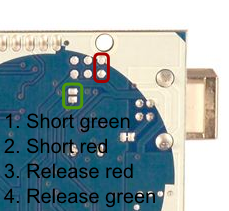
A bit of research suggested an updated Atmega 8u2 firmware (the usb chip). (also the new boards appear as /dev/ttyASM0 instead of /dev/ttyUSB0 - update to the latest RXTX libraries.

Borrowed from a forum post by stimmer on this thread

I saw that a new Uno firmware had been uploaded to the Arduino repository. I've been trying it out, it seems pretty good so far, tools menu and serial monitor are much more reliable and it only failed to program once. (Although the Duemilanove was never perfect either)

I got the firmware from here:
https://github.com/arduino/Arduino/tree/master/hardware/arduino/firmwares/arduin...(click on the right firmware, then click raw, then save it)

Reflashing the firmware on the 8u2 is a little tricky. Don't try this unless you are prepared to risk bricking your board completely!

You need the dfu-programmer utility:
sudo apt-get install dfu-programmer

Then follow the instructions here to get the Uno into DFU mode:
http://www.arduino.cc/cgi-bin/yabb2/YaBB.pl?num=1285962838/10#10

Then to flash the firmware, do this:
sudo dfu-programmer at90usb82 erase
sudo dfu-programmer at90usb82 flash --debug 1 Arduino-usbserial-uno.hex
sudo dfu-programmer at90usb82 reset

Finally unplug the USB plug, wait a few seconds, plug back in.


Also, a good page on the arduino site

Note, that to put reset the Mega 8u2 chip, the reset pins are a bit different: I found instructions for resetting the mega chip.


My mega's accepted the sketches without problem, and both replicatorG and RepRap host connect well at 115200 baud.

Might help if you're getting unreliable high-speed connections to the arduino and you've got a recent board (/dev/ttyACM0)

Tuesday, 1 November 2011

Arduino Mega board is toast!

I have managed to blow my Arduino mega board.
It stopped uploading, and there was a 'hot' smell - never a good sign. Unplugging everything, the arduino chip was very hot indeed.

After waiting for it to cool, I found that plugging it into the USB socket - nothing else - started to make the mega chip warm up, and it got too hot to touch. :-(
Another circuit board is sacrificed to the gods of knowledge and experience.

Tracing things back, I wondered how it happened. My setup hadn't changed, I'd just been running heater and extruder tests - the steppers weren't plugged in, so it was unlikely to be them.

Looking at the my heater board again, I realised that the output pin of the arduino was connected straight to ground through the MOSFET gate - no current limiting resistor. A bit of digging uncovered a possible problem - the design I'd used as a base (RepRap Gen 2/3) had the same circuit, but used current limiting Mosfets. I'd upgraded mine to larger ones, but checking the data sheet, the Mosfet gate acts a bit like a capacitor. Charging the gate could be done slow(with a resistor) or fast. A current of 2A was given as an example to charge the gate in 14nS.

Oh. The arduino pins can only handle 100mA or so. Still, it only does that when it's switched on or off, so long as I wasn't switching it on and off thousands of times a second - like using PWM.... Damn.

Looking back, it's surprising that it coped as well as it did - it should have gone up in smoke straightaway! I'm impressed it worked at all  - it coped for several hours of testing. Each time it switched, the arduino pin was directly connected to ground - drawing a big current for a few mS, then when it switched off, the mosfet gate would discharge itself straight through the arduinio pin to ground.

I have now redesigned my heater / Mosfet board to incorporate a 560ohm current limiting resistor (between the arduino pin and the mosfet gate), and also a pull-down 100k resistor between the Mosfet gate and ground. It should limit the current to 90mA, and make sure the gates switch off if the board isn't connected.

I've also ordered a couple of new Ardunios - hopefully I'll be more careful with these...
:-)

Sunday, 4 September 2011

One step forward...

I spent the last couple of days fiddling with software and firmware.
I started with the 'official' RepRap host and firmware, but since I've got a complete mix of electronics (single Arduino mega, self-designed mega shield, separate extruder boards (X,Y, Z, E) and custom heater board), I needed to update all of the pin assignments and configuration files.

I made reasonable progress, managed to get the XYZ axes working fine, but it refused to turn the extruder stepper. I tried various things, ( including heating extruder to 200C), but it refused to move.
I then tried to get the latest host / firmware from git, but while doing this managed to mess up my java3d configuration slightly. Now, all I get is :

DEBUG: Attempting to initialize Arduino/Sanguino [0.174s/87ms]
Exception in thread "J3D-Renderer-1" java.lang.UnsatisfiedLinkError: javax.media.j3d.NativeScreenInfo.openDisplay()J
        at javax.media.j3d.NativeScreenInfo.openDisplay(Native Method)
        at javax.media.j3d.NativeScreenInfo.getStaticDisplay(NativeScreenInfo.java:48)
        at javax.media.j3d.NativeScreenInfo.isGLX13(NativeScreenInfo.java:36)
        at javax.media.j3d.NativeConfigTemplate3D.getBestConfiguration(NativeConfigTemplate3D.java:67) 
... 
I've tracked this down to a missing j3d*.so file. I have tried a number of things (setting LD_LIBRARY_PATH, java.library.path, putting the .so files in the current directory, etc) but there is also a problem with 64/32bit libraries. Downloading latest versions of the libraries, etc also didn't help :-(. I think it is more subtle than just missing the .so file in the path.

I switched to use replicatorG - nice program - but the 5d firmware still didn't move the extruder (after fixing some baud rate problems).

Finally, I updated to the 'Sprinter' firmware - slightly easier to configure - and this, in conjunction with the ultimaker version of replicatorG, allows me to move the extruder stepper!! woohoo!

Now, to test the heater/extruder, configure the parameters, connect up the axes...

Edit:
Oops. Nothing to do with firmware problems, just some dodgy intermittent connections on my stepper. Unplugging the mega during the firmware 'upgrade' wobbled the wire, making it work the next time...
Nothing to do with the firmware versions!!!
Wednesday, 9 June 2010

Friday, 4 June 2010

Renoir's Mega Shield built

I've been soldering and building and I've finished my mega shield!
From RenoirsMegaShield
The build went well. I 'tinned' the copper pads (using some plumbing flux and a tiny bit of solder), which made the soldering a bit easier. Using a tip (from ladyada?) I converted some standard header pins to some through-pins by pushing them through using the flat on a pair of pliers, three or 4 at a time:
From RenoirsMegaShield
Once I'd fixed the pins, I could put them through into the arduino and check the alignment - OK. I left the pins partially pushed in to maintain the position, and soldered a single pin from each row:
From RenoirsMegaShield
This held them in place when I removed the mega and soldered the rest.
From RenoirsMegaShield
I've now got 10-pin IDC headers for X,Y,Z, and extruder (A) - and a spare (B) using header pins as I ran out of sockets. There's a space for the 20-pin interface connector from the generation 4 designs, and a whole set of +5v/GND/analog in headers for temperature probes, extra sensors, etc. Along the top is an I2C 4-pin header, and similar +5v/GND/digital I/O headers for servos, TX/RX comms, and some PWM pins. 8 PWM outputs are taken to a separate 10-pin IDC header that is intended to go to a MOSFET power driver board to drive the heater and heated bed (coming soon).

Monday, 31 May 2010

Mega RepRap sheild

I've been working for a couple of weeks on a RepRap Arduino Mega shield. I've got a mix of early generation 2 electronics, a few home-made single sided generation 3 stepper boards, and old arduino with a screw-terminal shield and a brand-new arduino mega.

I designed myself a version of an arduino mega shield to connect the gen3 stepper boards using the 10-pin IDC cables, and it might be useful for anyone transitioning between generations of electronics. Headlines:
  • Single-sided for home-made boards
  • 5 stepper driver headers - x,y,z,a,b - should match existing gen3 electronics.
  • (future-proof?) UI interface header that *should* match gen4 electronics.
  • Heater 10-pin IDC (to plug in MOSFET driver board later) - should be able to drive a reprap setup with 1 or 2 extruders/ heated bed without an additional extruder board.
  • I2c header as per standard boards
  • Optional extra 3-pin headers for digital in\out and analog in : +5v, GND, and data pin. This makes it easy to add temperature sensors, kill switches, extra limit switches, etc (I'm only using the min endstops).
If you think it might be useful, the files are here :
Eagle files for Renoir's RepRap Mega Shield

I've just etched one using my laserprinter/laminator method, and I've just etched two more single-sided stepper drivers. I'll post some photos once it's been assembled.

p.s. All files (and anything on this blog) available under creative commons attribution 3.0 licence.
:-)

Thursday, 18 March 2010

UK Suppliers

Recently, I've come across a couple of parts that might be useful to UK RepRappers.

I found a stepper driver board from DIY CNC

It's based on the A3977 stepper driver chip, like the version 3 of the RepRap stepper driver board. It has handy dipswitches to select down to 1/8 stepping, and handles up to 2.5 amps. There are screw terminals for the connections and an optional edge connector. Although the recommended voltage is 24v+, I've contacted the chap, and he says it should work down to 10v - and the board design seems pretty similar to the 12v RepRap boards. One board is £27 but there's a discount for buying 3 or 4 for a Mendel. Certainly worth a look as an alternative to a polulu-type board imported from the states, if MakerBot is out of stock.

I've just finished building a single-sided SMD version of the 2.3 stepper driver, and I've got the parts for a few more, so I haven't tried these personally.

On the other hand, I did buy an Arduino mega for £25 from D-Robotics from an Ebay auction. Arrived after a couple of days, seems to be a 'clone' of the reference design from a hong kong/chinese company.
From SMD_stepper

Plugged in, recognized as an arduino mega, example sketch loaded straight off.

Should be a good upgrade from my Gen2 (arduino) electronics: I should be able to load in the 5D firmware, unplug my breakout shield from the arduino and plug in the Mega!

Tuesday, 16 March 2010

Arduino Mega Shield

I'm fiddling with an eagle design for a RepRap arduino mega shield. I couldn't find any eagle files for the basic sheild pins, so here's one I ripped from the arduino reference design.

Arduino Mega Shield Eagle Files