Showing posts with label stepper drivers. Show all posts

Tuesday, 4 May 2010

Mendel home-made stepper boards

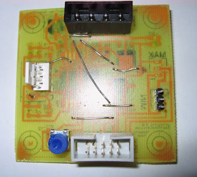
A productive weekend: I used the laserprinter technique to make four more single-sided stepper drivers.
I experimented with plain paper, baking paper, greaseproof paper, oiled paper, but the best transfers were with my cheap label backing paper.
To economise on the amount of label paper, I cut a section roughly a bit larger than the PCB, and stuck it to a clean A4 sheet with some of the discarded stickers. This then goes through the laserprinter.
From StepperPCBs

I then took off this section, bent it over the PCB and taped it down, then ran it through my laminator a couple of times. This transferred the toner to the PCB.
From StepperPCBs

After etching, I had four new stepper boards to build
From StepperPCBs

Monday, 22 March 2010

SMD - it ain't so hard!

I soldered my first surface mount board successfully! It was a lot easier than I expected...
I thought I'd write up my novice guide to SMD soldering, so any other novices have the confidence to get started.

Step 1 - get organised
I found a beading box from the local market stitching/craft stall had plenty of small boxes for my smd components. I labelled the blank strips as I took them out of the labelled bags, marking the component values several times along their length, because if they get mixed up the numbers are too small to read without a magnifying glass. Sort out and safely store the components. I marked each box with the value and the component number (R3, C4, etc) using post-its.
From SMD_stepper
Clean and scrub the circuit boards, so the copper is perfectly clean and ready to accept the solder. I used a trusty green scourer and Cif cleaner(light abrasive).
I also used the laserprinter method to print the silkscreen layer to make it easier to place the components.
From SMD_stepper

Step 2 - Working space and tools

Sort out a working space. I used several sheets of A4 paper taped together, because components show up well against them.
From SMD_stepper
While placing, I needed some kitchen/loo roll to wipe the solder paste off tools. I also used:
From SMD_stepper
Solder paste, a couple of pairs of tweezers (the curved point ones are best), and a sharp knife. Printout a large copy of the PCB diagram with the component layout, and a separate list of the component values and numbers. It's much easier to double check before you solder, not after.
From SMD_stepper
A magnifying glass is essential. Luckily, my wife had a nice big glass on a flexible mount for her cross-stich, so I could borrow that.

Step 3 - Solder paste
Add a tiny amount of solder paste to each pad. I went with the absolute minimum, thinking it wuould be easier to add more later than remove it - but it was more than enough. I ended up using the point of the tweezers and the point of the knife to move extra paste from pad to pad. For the IC, I spread a line of paste all along the pins, and then used the blade to split each individual pads apart, cutting a gap between individual pads.

Step 4 - Place Components
Gently peel apart the film from the carrier, and tap the components onto the paper. Using the tweezers, place the components onto the pasted pads. Check and double-check the values or labels, and check the diagram to make sure of the positioning. Getting perfect alignment is not essential, but make sure the electrical contacts will be correct.

Step 5 - Apply heat
Lots of internet advice talks about temperature controlled ovens, customized hotplates, etc. I haven't got any of that, so I whacked it on my electric cooker ring.
From SMD_stepper

I'm not recommending this, although it worked for me (although I seem to have cooked a couple of green LEDs). The solder paste starts off a murky grey but when the solder hits temperature, it suddenly becomes a nice shiny solder joint and pulls the components into place.
I put the board on a cold cooker ring, turned it to 6 (full) and watched it. Once the joints popped, I quickly checked them (one corner was slightly raised, pressing it down with the tweezers popped the last few joints) and when they were all done, turned it off. After it had cooled enough to touch, I moved it and let it cool completely.

Inspection photos:
From SMD_stepper

Step 6 - Remaining through-hole components
I soldered the remaining through-hole components (mainly connectors) and added some wire bridges, because I only have a single sided board. This is also why the SMD components are on the bottom and the through-hole are on top.
From SMD_stepper
A couple of the green LEDs don't work, and the 4-pin connectors I have are the wrong size, and the 10-pin IDC connector has ended up reversed, but I wired it up to an arduino and a NEMA-17 stepper and it runs the stepper fine. All in all, a good experiment.

I'll fix the board and run off a few more for my Mendel - I've got enough components for four more stepper boards. Single-sided eagle files are available and are based on the stepper driver 2.3 from MakerBot.

Thursday, 18 March 2010

UK Suppliers

Recently, I've come across a couple of parts that might be useful to UK RepRappers.

I found a stepper driver board from DIY CNC

It's based on the A3977 stepper driver chip, like the version 3 of the RepRap stepper driver board. It has handy dipswitches to select down to 1/8 stepping, and handles up to 2.5 amps. There are screw terminals for the connections and an optional edge connector. Although the recommended voltage is 24v+, I've contacted the chap, and he says it should work down to 10v - and the board design seems pretty similar to the 12v RepRap boards. One board is £27 but there's a discount for buying 3 or 4 for a Mendel. Certainly worth a look as an alternative to a polulu-type board imported from the states, if MakerBot is out of stock.

I've just finished building a single-sided SMD version of the 2.3 stepper driver, and I've got the parts for a few more, so I haven't tried these personally.

On the other hand, I did buy an Arduino mega for £25 from D-Robotics from an Ebay auction. Arrived after a couple of days, seems to be a 'clone' of the reference design from a hong kong/chinese company.
From SMD_stepper

Plugged in, recognized as an arduino mega, example sketch loaded straight off.

Should be a good upgrade from my Gen2 (arduino) electronics: I should be able to load in the 5D firmware, unplug my breakout shield from the arduino and plug in the Mega!

Sunday, 28 February 2010

Schoolboy Error

In my last two boards, I made a schoolboy error:
Both boards (due to different reasons) ended up being reversed left-to-right.
Now, during the transfer from paper to the board, it does mirror/reverse the image. I had 'overcompensated' and flipped the board twice, i.e. the wrong way.

Also, the stepper driver experiment was for the brand new 3.0 version, not the tried and tested 2.3 version (as noticed in the comments).

I've knocked together a version of a single sided board for the stepper driver v2.3 here - you want the v2 for the 2.3 board (eagle and .brd files provided). I dropped the ethernet connections (too many holes) and reverted back to the RepRap 3-pin connectors for the max/min endstops.

Here's a couple of etched boards, using the laserprinter/laminator/dab etching method:
From PCB
From PCB
I had to tidy a couple of edge tracks with a CD pen, but they came out well.

Here's my temperature controller (0-100 degrees C, controlling a relay) for another project:

From PCB
I bought some more copper board today from Maplins, so I should be able to make them a bit larger next time and avoid the issues with the transfer at the edge of the board.
Now to drilling several hundred holes with my new dremmel...

Saturday, 20 February 2010

Etched boards

Here's the two boards I etched using the laserprinter/laminator method.

From PCB


From PCB


The laminator bound the laser toner to the boards really well. I used a few mm of ferric chloride, and dabbed/rubbed it onto the board with a cotton wool ball (wearing GLOVES). The centre etched first, and I was able to rub more around the edges to finish off the etch.

The etching worked really well. The detail came out fantastically - even the drill marks came out on the stepper board. You can also clearly see a minature mouse pointer in the centre of the temperature board - oops!

The toner bound so well to the copper that I had to scrub the completed boards with a green scourer and cif to get the toner off - it was harder work than cleaning the boards in the first place!
There is a small error on the stepper board (bottom left corner, just above the resistors). When transferring the laserprint to the board, before the laminator, I accidentally smudged a track. This is probably repairable when I add the via/wire bridges.

[Edit - I thought this was based on the Makerbot stepper driver (A3982) - but I actually picked up the files from the RepRap distribution, which are actually V3.0 of the stepper driver, based on the A3977. Wow, I'm ahead of the curve!]
Schematic:
From PCB

Thursday, 11 February 2010

New toys - baby steppers!

Kickstarting my RepRap project again, I splashed out on four NEMA 17 stepper motors from Zapp Automation - four SY42STH47-1684B motors. Good service, arrived quickly and well packed.

I needed a stepper for an extruder, so I got 4 to give an easy upgrade path to a mendel.

I'm currently running on generation 2 electronics, so I also need another stepper driver. The gen3 boards are great, but they are out of stock at the moment, and because they're fully populated, they would replace my current setup - not a problem, but an expensive upgrade.

While looking around, I found a couple of other posts on this subject:


Casainho also grabbed one of these motors
and is looking at driving it with a Pololu Stepper driver board.

Bothacker posted about his electronics setup which uses Sparkfun driver boardscontrolled by a Seeduino Mega.

I really like BotHacker's approach. It's modular, so it's easier to upgrade and slightly more flexible for re-use on other projects, and the seeduino/arduino split for extruder heads can be skipped to start with (as most only have one working extruder) and added later if required. It woul probably be more expensive overall, but is probably more readily available - the driver boards are replacable by other manufacturers, other mega/seeduino controllers can be plugged in. The connector boards are easier to design and manufacture at home, reducing the bottleneck of available boards.

I'm currently leaning towards BotHacker's approach.