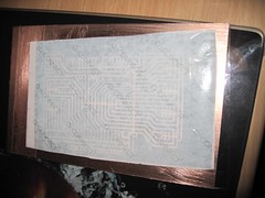
I've been using the laser toner method for a while to make my PCBs. It seems to work well for me, I print out the PCBs using a Samsung ML2010 laser printer, tape them to a cleaned copper board, then run them through a laminator twice. The heat fuses the toner to the board, and as long as your paper isn't too sticky, you can peel it straight off and etch.
I've been using this successfully, even for larger boards like my Arduino mega shield. The key variable seems to be the paper. I have the best results by cutting a square of sticker backing paper, using the stickers to stick it to the centre of a normal sheet of paper, then printing the PCB from Eagle. This works well, but I do need a sheet of stickers (like the A4 laser printing stickers) every time.
Other people have reported success with tracing paper, or magazine paper. I grabbed some tracing paper (two types, Goldline 63gsm and Goldline 112gsm) paper and gave it a try. It printed well, but didn't stick too well - you need to soak the paper to remove it, and most of my toner came off with the paper. Maybe my laminator wasn't hot enough :-(.
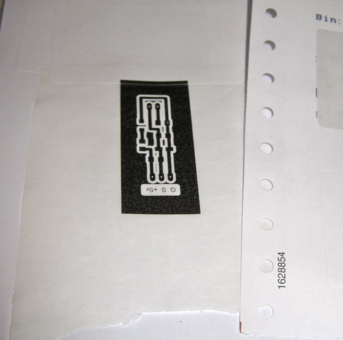
So, I'd run out of labels, my tracing paper experiments weren't working well - and then my eye fell on a discarded Farnell packing bill on my table. The Farnell packing receipts are printed on some sort of fan-fold sticker paper so that the address labels can be removed and stuck to the box. The whole bill is basically one big sticker! I cut a square, stuck it to a sheet of paper using the sticker I'd just removed, and ran it through the printer.
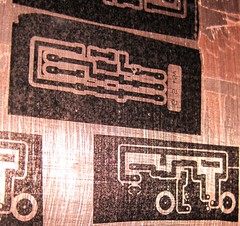
Perfect result, first time! The toner transferred very well to the board:
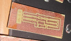
The finished board (a SMT version of the tiny thermistor circuit) looks great and from the detail (on the lettering) this would work with much finer traces!
I'll start saving up all my old shipping receipts instead of buying printer labels now....
P.S. top tip - after the stickers have been 'laminated' and cooled, if you gently rub the back of the sticker with your thumb, a small 'bubble' forms that gently lifts the sticker backing away from the toner bit by bit. I get almost 100% adhesion with this technique.
After a few days, my new crimping toys tools arrived in the post.
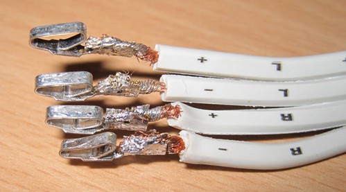
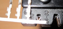
Here's a joint from a couple of years BC (Before Crimptool) :
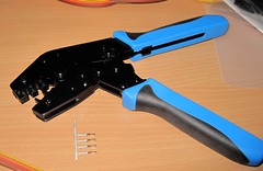
However, that was before the RVFM HT-225D, which I got from Rapid.
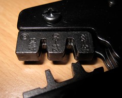
It has the correct 'B' shaped jaws to make proper crimp joints:
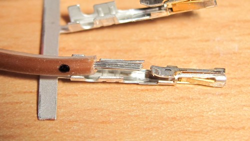
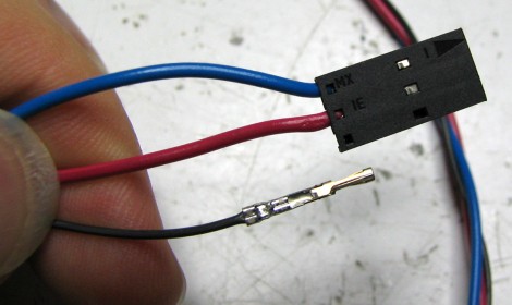
To use this effectively, you need a set of crimp pins, and you need to carefully strip and trim the wire, like this :
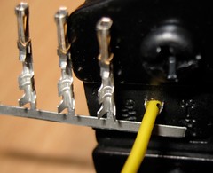
Then you need to insert a crimp pin into the appropriate jaws - note you don't always need to remove them from the strip, I found them easier to handle by bending a single pin away from the strip.
Then, insert the wire : I marked a small dot with a sharpie to mark the appropriate depth:
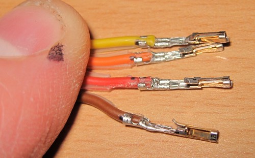
Pull the handles together until they're all crimped - rinse and repeat:
So much easier and more efficient than the manual pliers/solder method. They're not 'perfect' yet - according to the spec I've got a little too much insulation in there - but it's a damn sight neater than my first attempts a couple of years ago :-).
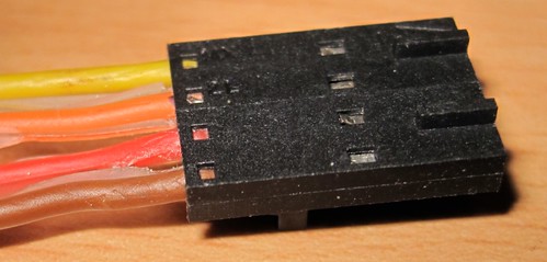
Completed Plug :
I must admit I wasn't that familiar with crimping before starting my RepRap. For the uninitiated, it's the method of attaching the wires to the various plugs to connect to the PCBs. The main connections are the 4-pin stepper motors and the 3-pin headers for the endstops. I also use a 3-pin connector for the thermistor sensor.
The connector consists of some metal pins with tabs, and the tabs are crimped onto the wires. The metal pins then fit into a plastic housing that makes the plug.
My early attempts involved squishing a bare wire between the tabs with some pliers. However, some of my crimped joints were not well attached: sometimes the pins would deform, so they didn't fit into the housing properly, and often the wire would either fall out, or I'd end up breaking some of the wire strands. I usually ended up squishing and then trying to solder them, often also melting the insulation.
This caused a recent problem where my extruder stepper was not moving - I thought it was due to the firmware, but it was actually a failing stepper connection - two of the wires had bad, intermittent connections.
Using my obsession to understand every part of my 'rap, I did some digging. Mr Nophead had an excellent video which solved my immediate problems :-
Time to bite the bullet and get a proper tool. Although you can spend over a hundred pounds on a crimping tool, every manufacturer has a slightly different tool, several different sizes and styles, and most are expensive.
After a bit more research, I found that the 'cheap' (<£15) muti-size crimping tools are only useful for automobile connectors (anything with three coloured dots on it - they are too large), 'bootlace ferrules' crimpers are also not suitable (wrong shape), and the telephone/RJ45 crimping tools are special. The 'molex' and other open crimping terminal styles we use are a lot smaller, typically described using wire gauges, e.g. 22-24AWG of 24-28AWG. However, I did find one reasonably cheap well-reviewed tool - the Multicomp HT225D - available from Rapid(£20) and Farnell(£37). The correct tools have a small 'B' shaped indent, which bends the tabs back on themselves to tightly hold the wire. A properly crimped joint does not need soldering and is more than strong enough for RepRapping connections.
Also worth noting is the huge variety of crimping pins, housings, gold/brass/tin platings, and huge number of options when you go looking to buy connectors. Note that certain pins fit certain housings - you need to make sure the pins, housings, sockets all come from the same range - there are a bewildering array - just see the molex site! The two Molex ranges I found most applicable to RepRapping were the KK range (cheap and cheerful, already used for the stepper and range sensors) and the SL range. Both are available in the 2.54mm (0.1 inch) pitch that the RepRap boards use for the endstops and I use for my steppers.
I personally prefer the SL crimping terminals (16-02-0088)- they look like they will connect better (holding from both sides) rather that the KK terminals that push one side against the housing. I also picked up some 3-way and 4-way housings for the terminals. According to the Molex site, they will use the 70058 range of pins, which include the 16-02-0088.
I went for the gold-plated terminals, as the header pins on my boards are already gold-plated, and the gold-plated terminals have a lifetime of 100 cycles (plugging and unplugging) - the tin ones only have 25 cycles. I also wanted some reasonably chunky wire for the steppers, so I got some 4-way 24AWG ribbon cable, which determined the size of the crimp terminals (22-24AWG) I needed.
I also picked up some male pins (16-02-0081) - so I can make some wire-to-wire connectors. Most of my wires have awful twisted and soldered bodges where they're connected together - covered with heatshrink when I remembered to put it on before soldering, and insulation tape when I didn't. I'd like to replace my bodges with proper pluggable connections, particularly with the stepper wires.
I hope this will fix my dodgy connection issues, and also will tidy my 'rap wiring up at the same time.
:-)