Well, 53 to be exact.
I've been looking around to collect Mendel parts for a little while, intending to reproduce from my BfB Darwin. I've picked up four nema17 steppers, built myself some stepper drivers and electronics, and I'm now looking for the mechanical parts. On the parts lists are a significant number of bearings, which can be quite pricey.
Luckily, I found RepRapKit.com, based in the UK, and ordered myself a complete set of bearings for less than 20 quid - much cheaper than everywhere else I've looked so far. Excellent service - I had a couple of emails with him and he seems like a really nice friendly chap. Parts were ordered and dispatched quickly, and delivered next day. I got 51 smaller bearings and two M8/skate bearings (including enough to make a geared/stepper extruder), they all look good and turn well. The store is selling ABS and bearings so far, and is looking to expand into extruders and other RepRap bits.
I also got round to blowing the dust off my BfB Darwin. It needs several bolts tightening and some general maintenance, and I disassembled the three stepper motors, covered them in plastic bags and tape, and ground out some proper flattened shafts using my dremmel. Note : metal filings from filing or grinding are not good inside a precision engineered bearing, and since they're highly magnetic, it does tend to attract the dust.
Make sure the bearings and motors are nicely covered (with blutack/tape/plastic bags) otherwise the dirty bearings will seize or grind away very quickly.
I'd had a go at filing the shafts back during the initial assembly, but didn't have the right tools - I did have a few problems with the axes slipping at times. Once it's all back together, it should be fine this time.
Tuesday, 13 July 2010
Friday, 25 June 2010
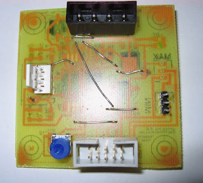
Heater board complete
I've completed and soldered my heater board.
There are 8 PWM outputs from my reprap shield which are boosted using 54A MOSFETS. These should happily drive my extruder heater, heated bed, fans, extra motors, whatever.
I've posted the files to thingiverse. I've also added my single-sided stepper driver files to a thing as well.
I now have four working stepper drivers, one mega shield, and a completed heater PWM board. Only a couple of thermistor sensors, and I'll have a complete set of electronics for a mendel :-)
Saturday, 19 June 2010
RepRap host software on Mac
Just a quick note to anyone trying to get the RepRap host software to run on a new Mac (Mac OSX 10.6.3).
The librxtxSerial.jnilib file supplied in the reprap software didn't seem to work. I found one at
http://iharder.sourceforge.net/current/java/ and I replaced it with this newer one.
type 'java org.reprap.Main'
This brings up the main reprap windows on my mac, and I was able to load and slice a .stl file. YMMV :-)
Doh!
This is usually true of any other command-line program, but any arguments AFTER the classname are passed to the class Main() method. I blame late-night programming :-)
Ignore all the java/extension rubbish, just use instructions from
http://tonybuser.com/reprap-host-on-osx-snow-leopard
A command line that also works is
I downloaded the software from the wiki and unzipped it.
To get it to work, I had some problems trying to make it accept a classpath. Eventually I did the following:
Make a directory ~/Library/Java/Extensions
Copy any files with *.jar and *.jnilib extensions to that directory.
The librxtxSerial.jnilib file supplied in the reprap software didn't seem to work. I found one at
http://iharder.sourceforge.net/current/java/ and I replaced it with this newer one.
Go to the reprap host software directory in a terminal window (you need to be in a directory with the rr-logo-green-url.png file in it).
type 'java org.reprap.Main'
This brings up the main reprap windows on my mac, and I was able to load and slice a .stl file. YMMV :-)
UPDATE:
As pointed out by Tony, this is not the most elegant solution. It doesn't help that I was looking at the 'mac-experimental' version from last year, rather that re-building from source :-( oops.
I also found out why I was having problems with the classpath :
java org.reprap.Main -cp $CLASSPATHis NOT equivalent to
java -cp $CLASSPATH org.reprap.Main
Doh!
This is usually true of any other command-line program, but any arguments AFTER the classname are passed to the class Main() method. I blame late-night programming :-)
Ignore all the java/extension rubbish, just use instructions from
http://tonybuser.com/reprap-host-on-osx-snow-leopard
A command line that also works is
java -cp "*" org.reprap.Main
Wednesday, 9 June 2010
First Thingiverse submission!
Rather than try and re-create thingiverse manually , I posted my RepRap Mega Shield to Thingiverse.
Enjoy!
Monday, 7 June 2010
Apple service and board PDFs
A few weeks ago, I bought myself an Apple MacBook Pro :-) and I've been really happy with it. However, a few days ago, I had terrible trouble trying to load the Ardunio software - segment faults and Kernel Panics (serious errors!) all over the place.
After a bit of debugging, I tracked it down to a single command - 'java -d32' which would cause a segmentation fault or bus error straightaway. A bit more investigation led me to the Apple Hardware test - which reported a 4MEM error, indicating a bad stick of ram :-(.
I dropped into the apple store today, expecting a delay as they had to send my nice new MacBook off, or at least swop out the ram. The apple 'Genius' was very helpful, and confirmed the bad ram - or possibly a logic board - and went off to speak to the manager.
However, 10/10 for service - despite the fact that I'd been using it for 6 weeks, they arranged a swop for a brand new machine right away! They even copied everything over to the new machine! I picked up my 'new' pc, opened the lid and everything was exactly as it had been on the old machine. I am now a very happy Mac customer :-) - that is an excellent example of customer service.
Also produced some PDF files for the Mega shield - available with the eagle files on the
Eagle files for Renoir's RepRap Mega Shield Page.
Friday, 4 June 2010
Renoir's Mega Shield built
I've been soldering and building and I've finished my mega shield!
The build went well. I 'tinned' the copper pads (using some plumbing flux and a tiny bit of solder), which made the soldering a bit easier. Using a tip (from ladyada?) I converted some standard header pins to some through-pins by pushing them through using the flat on a pair of pliers, three or 4 at a time:
Once I'd fixed the pins, I could put them through into the arduino and check the alignment - OK. I left the pins partially pushed in to maintain the position, and soldered a single pin from each row:
This held them in place when I removed the mega and soldered the rest.
I've now got 10-pin IDC headers for X,Y,Z, and extruder (A) - and a spare (B) using header pins as I ran out of sockets. There's a space for the 20-pin interface connector from the generation 4 designs, and a whole set of +5v/GND/analog in headers for temperature probes, extra sensors, etc. Along the top is an I2C 4-pin header, and similar +5v/GND/digital I/O headers for servos, TX/RX comms, and some PWM pins. 8 PWM outputs are taken to a separate 10-pin IDC header that is intended to go to a MOSFET power driver board to drive the heater and heated bed (coming soon).
From RenoirsMegaShield |
Monday, 31 May 2010
Mega RepRap sheild
I've been working for a couple of weeks on a RepRap Arduino Mega shield. I've got a mix of early generation 2 electronics, a few home-made single sided generation 3 stepper boards, and old arduino with a screw-terminal shield and a brand-new arduino mega.
I designed myself a version of an arduino mega shield to connect the gen3 stepper boards using the 10-pin IDC cables, and it might be useful for anyone transitioning between generations of electronics. Headlines:
Eagle files for Renoir's RepRap Mega Shield
I've just etched one using my laserprinter/laminator method, and I've just etched two more single-sided stepper drivers. I'll post some photos once it's been assembled.
p.s. All files (and anything on this blog) available under creative commons attribution 3.0 licence.
:-)
I designed myself a version of an arduino mega shield to connect the gen3 stepper boards using the 10-pin IDC cables, and it might be useful for anyone transitioning between generations of electronics. Headlines:
- Single-sided for home-made boards
- 5 stepper driver headers - x,y,z,a,b - should match existing gen3 electronics.
- (future-proof?) UI interface header that *should* match gen4 electronics.
- Heater 10-pin IDC (to plug in MOSFET driver board later) - should be able to drive a reprap setup with 1 or 2 extruders/ heated bed without an additional extruder board.
- I2c header as per standard boards
- Optional extra 3-pin headers for digital in\out and analog in : +5v, GND, and data pin. This makes it easy to add temperature sensors, kill switches, extra limit switches, etc (I'm only using the min endstops).
Eagle files for Renoir's RepRap Mega Shield
I've just etched one using my laserprinter/laminator method, and I've just etched two more single-sided stepper drivers. I'll post some photos once it's been assembled.
p.s. All files (and anything on this blog) available under creative commons attribution 3.0 licence.
:-)
Monday, 17 May 2010
Useful PCB notes
http://www.electricstuff.co.uk/pcbs.html
Nice clear semi-pro PCB instructions :-)
Useful suggestions for PCB-making services
Nice clear semi-pro PCB instructions :-)
Useful suggestions for PCB-making services
Tuesday, 4 May 2010
Home-made Steampunk cogs
I like the steampunk look, and my daughter and I fancy building a steampunk keyboard.
Alongside my PCB building, I tried building some steampunk-style cogs to use as decoration or parts. I found some thin copper foil (0.1mm) from a sculptor's and restoration supplier Tiranti.
It's nice stuff, thin enough to cut with scissors, but thick enough to cover corners and bend around shapes without ripping. It should cover keyboard edges well.
One of the things I wanted to try was to use PCB etching techniques to make complex cogs or clockwork shapes. I put together a couple of templates (see the end of this post) and tried a few things to transfer the toner onto the foil - the best technique ended up being the label backing paper as per PCBs. Because you need to cover both sides, I mirrored the label and folded it in half - then placed the copper foil inside the transfer.
A couple of passes through the laminator, and the toner is fused onto the copper. I also printed a more complex mechanism onto normal PCB board.
I then used standard ferric chloride (PCB etching fluid) to etch the copper. You can either dunk the boards and gently stir the etchant, or (with GLOVES) rub it on the board with cotton wool or a kitchen towel.
Etching the PCB was pretty quick: etching the foil all the way through took a about twice as long as the PCB board. The etching worked well, most of the complex detail and cog teeth coming out well.
However, the toner is much more difficult to remove. With the PCB, the board gives the copper plenty of strength so the toner can be scrubbed away. With the foil cogs, they tear easily, so you can't scrub them. I tried soaking in acetone (nail varnish remover) and this removed some, but not all the toner. An agitated acetone bath (maybe an ultrasonic jewellery cleaner?) might remove more.
The normal PCB came out very well. The detail is good and the board can be scrubbed to remove all the black toner.
One of my ideas was to place some LEDs behind the PCB to shine through the board, illuminating the hidden pattern: this backlighting does give a really nice effect (shown against a normal lamp).
A nice large panel with plenty of clockwork mechanisms would look good instead of a numeric keypad, or as a lit panel in a PC case. Layers could even be stacked for a greater 3-d effect. This is just the research so far, I'll post more as it proceeds.
How to make a gear template (examples)
Alongside my PCB building, I tried building some steampunk-style cogs to use as decoration or parts. I found some thin copper foil (0.1mm) from a sculptor's and restoration supplier Tiranti.
From Steampunk cogs |
One of the things I wanted to try was to use PCB etching techniques to make complex cogs or clockwork shapes. I put together a couple of templates (see the end of this post) and tried a few things to transfer the toner onto the foil - the best technique ended up being the label backing paper as per PCBs. Because you need to cover both sides, I mirrored the label and folded it in half - then placed the copper foil inside the transfer.
From Steampunk cogs |
I then used standard ferric chloride (PCB etching fluid) to etch the copper. You can either dunk the boards and gently stir the etchant, or (with GLOVES) rub it on the board with cotton wool or a kitchen towel.
Etching the PCB was pretty quick: etching the foil all the way through took a about twice as long as the PCB board. The etching worked well, most of the complex detail and cog teeth coming out well.
However, the toner is much more difficult to remove. With the PCB, the board gives the copper plenty of strength so the toner can be scrubbed away. With the foil cogs, they tear easily, so you can't scrub them. I tried soaking in acetone (nail varnish remover) and this removed some, but not all the toner. An agitated acetone bath (maybe an ultrasonic jewellery cleaner?) might remove more.
From Steampunk cogs |
A nice large panel with plenty of clockwork mechanisms would look good instead of a numeric keypad, or as a lit panel in a PC case. Layers could even be stacked for a greater 3-d effect. This is just the research so far, I'll post more as it proceeds.
How to make a gear template (examples)
- Generate a gear at woodgears.ca - I used tooth spacing 6mm, gear 1 teeth 100, spokes 5 and show spokes on.
- Hit the 'print' button, then OK. My mac then allowed me (bottom left PDF dropdown) to import the PDF into iPhoto, basically exporting it to a jpg.
- Edit the picture in Gimp. I did the following operations:
- Fill the outline with black
- Use Select - by color and then click on the background (white)
- Use Select - shrink to shrink the selection by 20 pixels (not from the image border)
- Use Edit - Fill with FG colour to fill it with black
- Use Select - all and Edit - copy
- Use Image - Canvas Size. Click the 'link' between the width and height to unlink them. Double the height and add two pixels.
- Click Image - transform - flip vertically
- Click edit - paste as - new layer. This should give you a mirrored image top and bottom, with a small line between them.
- Click file - save and export when prompted.
- Fill the outline with black
- Laserprint onto label backing paper, heat transfer to copper foil, and etch.
Mendel home-made stepper boards
A productive weekend: I used the laserprinter technique to make four more single-sided stepper drivers.
I experimented with plain paper, baking paper, greaseproof paper, oiled paper, but the best transfers were with my cheap label backing paper.
To economise on the amount of label paper, I cut a section roughly a bit larger than the PCB, and stuck it to a clean A4 sheet with some of the discarded stickers. This then goes through the laserprinter.
I then took off this section, bent it over the PCB and taped it down, then ran it through my laminator a couple of times. This transferred the toner to the PCB.
After etching, I had four new stepper boards to build
I experimented with plain paper, baking paper, greaseproof paper, oiled paper, but the best transfers were with my cheap label backing paper.
To economise on the amount of label paper, I cut a section roughly a bit larger than the PCB, and stuck it to a clean A4 sheet with some of the discarded stickers. This then goes through the laserprinter.
From StepperPCBs |
I then took off this section, bent it over the PCB and taped it down, then ran it through my laminator a couple of times. This transferred the toner to the PCB.
From StepperPCBs |
After etching, I had four new stepper boards to build
From StepperPCBs |
Wednesday, 28 April 2010
Cats and chips
Seeing as I've seen a few other RepRappers with cats, I thought I'd introduce mine to the internet:
We started with Jess, who's now a bit old and grumpy, mainly because of the two newbies.
Recently, we've given a home to two more kittens from the rescue home, two brothers, Harry and Oscar. Here's Jess and Harry:
And here's Oscar - who appears to be made of rubber :-)
With three cats, we go through a lot of catfood. In fact, we were going through 3 pouches morning and evening + two big bowls of dry food. However, after a while we found that it wasn't just down to ours. Jess is very nervous, and runs rather than confront other cats, and Oscar and Harry are very friendly, which even extends to other cats in the area. Several evenings we saw other neighbourhood cats wandering into our house - we even ended up naming them. FatCat was a big tomcat, who could barely fit through the flap: GreyCat was an adult long-haired grey, and black kitten frequently comes to play with Oscar and Harry in the garden. Most mornings, as I came down, the catflap would bang as someone left and all the foodbowls would be empty.
So, what's a computer nerd to do? As usual, I found a high-tech solution. PetPorte make a cat-flap that has a built-in chip reader, so it can identify your cats and open the door for them, while keeping the others out. Oscar and Harry were already chipped (Neutering and chipping is part of the rescue deal), and Jess got chipped at the local vets for £30, since it's a good idea anyway. Chipping is a tiny RFID tag injected into the back of the neck - the ID number is linked to a database with your name and address if your cat ever gets lost.
The catflap looks pretty normal - it's just got a covered 'porch' on the outside, containing a coil to read the RFID tags. Pics: Inside is pretty normal, just a small mains wire to the plug.
Cat's eye view from outside - you can see the coil in the porch used to read the tags.
Once an authorised cat goes under the reader, the flap unlocks for a few seconds, so it can come in, then re-locks (out only) so others can't follow it. There's also some extra features if you want, like a light sensor that doesn't allow them out after dark, and 'vet mode' - i.e. in only. It runs off a standard mains plug and/or a 9v pp3 battery backup.
It's a bit expensive, compared to other systems (like magnetic collars, etc) but it does exactly what it says on the tin. It will read our cats as soon as they're under the reader, and all three have been using it successfully for the last several days. It's well suited to Oscar, as he's lost four collars in the last three months - he tends to leave then in trees while climbing. You do have to 'scan' your cats the first time - it has a learning mode (half a minute to scan a new RFID tag) for each one. Both Harry and Oscar were so interested while I was installing it, they were picked up straightaway. Jess hisses when I pick her up, but it only took a second to scan her, then she stalked off in disgust.
It's been working perfectly so far - none of the intruders have been in, and the food bill has been cut by about half, plus Jess is a bit happier now the other cats are confined to the outside.
Pretty successful so far - I wonder if they do a human version? Children do lose keys so often... :-)
UPDATE:
Catflap in action: Black kitten has just tried to follow Harry in, but isn't allowed:
We started with Jess, who's now a bit old and grumpy, mainly because of the two newbies.
From Cats |
From Cats |
From Cats |
So, what's a computer nerd to do? As usual, I found a high-tech solution. PetPorte make a cat-flap that has a built-in chip reader, so it can identify your cats and open the door for them, while keeping the others out. Oscar and Harry were already chipped (Neutering and chipping is part of the rescue deal), and Jess got chipped at the local vets for £30, since it's a good idea anyway. Chipping is a tiny RFID tag injected into the back of the neck - the ID number is linked to a database with your name and address if your cat ever gets lost.
The catflap looks pretty normal - it's just got a covered 'porch' on the outside, containing a coil to read the RFID tags. Pics: Inside is pretty normal, just a small mains wire to the plug.
From Cats |
From Cats |
It's a bit expensive, compared to other systems (like magnetic collars, etc) but it does exactly what it says on the tin. It will read our cats as soon as they're under the reader, and all three have been using it successfully for the last several days. It's well suited to Oscar, as he's lost four collars in the last three months - he tends to leave then in trees while climbing. You do have to 'scan' your cats the first time - it has a learning mode (half a minute to scan a new RFID tag) for each one. Both Harry and Oscar were so interested while I was installing it, they were picked up straightaway. Jess hisses when I pick her up, but it only took a second to scan her, then she stalked off in disgust.
It's been working perfectly so far - none of the intruders have been in, and the food bill has been cut by about half, plus Jess is a bit happier now the other cats are confined to the outside.
Pretty successful so far - I wonder if they do a human version? Children do lose keys so often... :-)
UPDATE:
Catflap in action: Black kitten has just tried to follow Harry in, but isn't allowed:
From Cats |
Sunday, 28 March 2010
Recycled Heated Bed
I finally put together an idea that I've had floating around for a while.
My wife had an old heated pad where the fabric had worn through. I took out the plug and element, and saved it, because I though it probably had some nichrome wire in the element.
Fast forward several months, to all this recent talk of headed beds.
I uncovered the element from my 'parts' box, and inspected it - the insulation is all intact, all well covered, no damage and safe. A careful test showed it still warmed up when plugged in.
I grabbed a couple of steel baking trays from Wilkinsons (£1 each) and my kapton tape.
I punched a hole in one of the trays, carefully bending the edges and masking them with tape so there were no sharp edges. I could then feed the element through and taped it to the back of the tray in a rough spiral with the kapton tape.
The other tray, I covered the base with strips of kapton tape, and placed over the element tray. VERY IMPORTANT: I added an earth wire grounding both of the trays to mains earth (the PSU case).
Hey presto, heated bed.
Firing it up, it reached 80C+ in a couple of minutes on 'full'. I haven't run it further than that without mounting it properly first.
Potential problems:
My wife had an old heated pad where the fabric had worn through. I took out the plug and element, and saved it, because I though it probably had some nichrome wire in the element.
Fast forward several months, to all this recent talk of headed beds.
I uncovered the element from my 'parts' box, and inspected it - the insulation is all intact, all well covered, no damage and safe. A careful test showed it still warmed up when plugged in.
I grabbed a couple of steel baking trays from Wilkinsons (£1 each) and my kapton tape.
From HeatedBed |
From HeatedBed |
From HeatedBed |
Firing it up, it reached 80C+ in a couple of minutes on 'full'. I haven't run it further than that without mounting it properly first.
Potential problems:
- Using Mains electricity - you need to be *very* careful and earth the case. Check your safety three times.
- I don't know what temperature it will reach: it needs to be mounted properly and tested. Temperature control is provided by the original power box - I can have 1, 2, or 3 and it will automatically switch off after 90 mins. (probably not a problem unless I'm doing a long print).
- The surfaces of the tins are relatively thin pressed steel. I suspect they're flat enough for 'small' prints (up to makerbot size) - I'll have to see if they're flat/rigid enough for larger objects.
- I could fill the thin gap between the element and the two plates with fire cement: it might improve heat conduction and possible help with stiffness/flatness.
Monday, 22 March 2010
SMD - it ain't so hard!
I soldered my first surface mount board successfully! It was a lot easier than I expected...
I thought I'd write up my novice guide to SMD soldering, so any other novices have the confidence to get started.
Step 1 - get organised
I found a beading box from the local market stitching/craft stall had plenty of small boxes for my smd components. I labelled the blank strips as I took them out of the labelled bags, marking the component values several times along their length, because if they get mixed up the numbers are too small to read without a magnifying glass. Sort out and safely store the components. I marked each box with the value and the component number (R3, C4, etc) using post-its.
Clean and scrub the circuit boards, so the copper is perfectly clean and ready to accept the solder. I used a trusty green scourer and Cif cleaner(light abrasive).
I also used the laserprinter method to print the silkscreen layer to make it easier to place the components.
Step 2 - Working space and tools
Sort out a working space. I used several sheets of A4 paper taped together, because components show up well against them.
While placing, I needed some kitchen/loo roll to wipe the solder paste off tools. I also used:
Solder paste, a couple of pairs of tweezers (the curved point ones are best), and a sharp knife. Printout a large copy of the PCB diagram with the component layout, and a separate list of the component values and numbers. It's much easier to double check before you solder, not after.
A magnifying glass is essential. Luckily, my wife had a nice big glass on a flexible mount for her cross-stich, so I could borrow that.
Step 3 - Solder paste
Add a tiny amount of solder paste to each pad. I went with the absolute minimum, thinking it wuould be easier to add more later than remove it - but it was more than enough. I ended up using the point of the tweezers and the point of the knife to move extra paste from pad to pad. For the IC, I spread a line of paste all along the pins, and then used the blade to split each individual pads apart, cutting a gap between individual pads.
Step 4 - Place Components
Gently peel apart the film from the carrier, and tap the components onto the paper. Using the tweezers, place the components onto the pasted pads. Check and double-check the values or labels, and check the diagram to make sure of the positioning. Getting perfect alignment is not essential, but make sure the electrical contacts will be correct.
Step 5 - Apply heat
Lots of internet advice talks about temperature controlled ovens, customized hotplates, etc. I haven't got any of that, so I whacked it on my electric cooker ring.
I'm not recommending this, although it worked for me (although I seem to have cooked a couple of green LEDs). The solder paste starts off a murky grey but when the solder hits temperature, it suddenly becomes a nice shiny solder joint and pulls the components into place.
I put the board on a cold cooker ring, turned it to 6 (full) and watched it. Once the joints popped, I quickly checked them (one corner was slightly raised, pressing it down with the tweezers popped the last few joints) and when they were all done, turned it off. After it had cooled enough to touch, I moved it and let it cool completely.
Inspection photos:
Step 6 - Remaining through-hole components
I soldered the remaining through-hole components (mainly connectors) and added some wire bridges, because I only have a single sided board. This is also why the SMD components are on the bottom and the through-hole are on top.
A couple of the green LEDs don't work, and the 4-pin connectors I have are the wrong size, and the 10-pin IDC connector has ended up reversed, but I wired it up to an arduino and a NEMA-17 stepper and it runs the stepper fine. All in all, a good experiment.
I'll fix the board and run off a few more for my Mendel - I've got enough components for four more stepper boards. Single-sided eagle files are available and are based on the stepper driver 2.3 from MakerBot.
I thought I'd write up my novice guide to SMD soldering, so any other novices have the confidence to get started.
Step 1 - get organised
I found a beading box from the local market stitching/craft stall had plenty of small boxes for my smd components. I labelled the blank strips as I took them out of the labelled bags, marking the component values several times along their length, because if they get mixed up the numbers are too small to read without a magnifying glass. Sort out and safely store the components. I marked each box with the value and the component number (R3, C4, etc) using post-its.
From SMD_stepper |
I also used the laserprinter method to print the silkscreen layer to make it easier to place the components.
From SMD_stepper |
Step 2 - Working space and tools
Sort out a working space. I used several sheets of A4 paper taped together, because components show up well against them.
From SMD_stepper |
From SMD_stepper |
From SMD_stepper |
Step 3 - Solder paste
Add a tiny amount of solder paste to each pad. I went with the absolute minimum, thinking it wuould be easier to add more later than remove it - but it was more than enough. I ended up using the point of the tweezers and the point of the knife to move extra paste from pad to pad. For the IC, I spread a line of paste all along the pins, and then used the blade to split each individual pads apart, cutting a gap between individual pads.
Step 4 - Place Components
Gently peel apart the film from the carrier, and tap the components onto the paper. Using the tweezers, place the components onto the pasted pads. Check and double-check the values or labels, and check the diagram to make sure of the positioning. Getting perfect alignment is not essential, but make sure the electrical contacts will be correct.
Step 5 - Apply heat
Lots of internet advice talks about temperature controlled ovens, customized hotplates, etc. I haven't got any of that, so I whacked it on my electric cooker ring.
From SMD_stepper |
I'm not recommending this, although it worked for me (although I seem to have cooked a couple of green LEDs). The solder paste starts off a murky grey but when the solder hits temperature, it suddenly becomes a nice shiny solder joint and pulls the components into place.
I put the board on a cold cooker ring, turned it to 6 (full) and watched it. Once the joints popped, I quickly checked them (one corner was slightly raised, pressing it down with the tweezers popped the last few joints) and when they were all done, turned it off. After it had cooled enough to touch, I moved it and let it cool completely.
Inspection photos:
From SMD_stepper |
Step 6 - Remaining through-hole components
I soldered the remaining through-hole components (mainly connectors) and added some wire bridges, because I only have a single sided board. This is also why the SMD components are on the bottom and the through-hole are on top.
From SMD_stepper |
I'll fix the board and run off a few more for my Mendel - I've got enough components for four more stepper boards. Single-sided eagle files are available and are based on the stepper driver 2.3 from MakerBot.
Thursday, 18 March 2010
UK Suppliers
Recently, I've come across a couple of parts that might be useful to UK RepRappers.
I found a stepper driver board from DIY CNC
It's based on the A3977 stepper driver chip, like the version 3 of the RepRap stepper driver board. It has handy dipswitches to select down to 1/8 stepping, and handles up to 2.5 amps. There are screw terminals for the connections and an optional edge connector. Although the recommended voltage is 24v+, I've contacted the chap, and he says it should work down to 10v - and the board design seems pretty similar to the 12v RepRap boards. One board is £27 but there's a discount for buying 3 or 4 for a Mendel. Certainly worth a look as an alternative to a polulu-type board imported from the states, if MakerBot is out of stock.
I've just finished building a single-sided SMD version of the 2.3 stepper driver, and I've got the parts for a few more, so I haven't tried these personally.
On the other hand, I did buy an Arduino mega for £25 from D-Robotics from an Ebay auction. Arrived after a couple of days, seems to be a 'clone' of the reference design from a hong kong/chinese company.
Plugged in, recognized as an arduino mega, example sketch loaded straight off.
Should be a good upgrade from my Gen2 (arduino) electronics: I should be able to load in the 5D firmware, unplug my breakout shield from the arduino and plug in the Mega!
I found a stepper driver board from DIY CNC
It's based on the A3977 stepper driver chip, like the version 3 of the RepRap stepper driver board. It has handy dipswitches to select down to 1/8 stepping, and handles up to 2.5 amps. There are screw terminals for the connections and an optional edge connector. Although the recommended voltage is 24v+, I've contacted the chap, and he says it should work down to 10v - and the board design seems pretty similar to the 12v RepRap boards. One board is £27 but there's a discount for buying 3 or 4 for a Mendel. Certainly worth a look as an alternative to a polulu-type board imported from the states, if MakerBot is out of stock.
I've just finished building a single-sided SMD version of the 2.3 stepper driver, and I've got the parts for a few more, so I haven't tried these personally.
On the other hand, I did buy an Arduino mega for £25 from D-Robotics from an Ebay auction. Arrived after a couple of days, seems to be a 'clone' of the reference design from a hong kong/chinese company.
From SMD_stepper |
Plugged in, recognized as an arduino mega, example sketch loaded straight off.
Should be a good upgrade from my Gen2 (arduino) electronics: I should be able to load in the 5D firmware, unplug my breakout shield from the arduino and plug in the Mega!
Tuesday, 16 March 2010
Arduino Mega Shield
I'm fiddling with an eagle design for a RepRap arduino mega shield. I couldn't find any eagle files for the basic sheild pins, so here's one I ripped from the arduino reference design.
Arduino Mega Shield Eagle Files
Sunday, 28 February 2010
Schoolboy Error
In my last two boards, I made a schoolboy error:
Both boards (due to different reasons) ended up being reversed left-to-right.
Now, during the transfer from paper to the board, it does mirror/reverse the image. I had 'overcompensated' and flipped the board twice, i.e. the wrong way.
Also, the stepper driver experiment was for the brand new 3.0 version, not the tried and tested 2.3 version (as noticed in the comments).
I've knocked together a version of a single sided board for the stepper driver v2.3 here - you want the v2 for the 2.3 board (eagle and .brd files provided). I dropped the ethernet connections (too many holes) and reverted back to the RepRap 3-pin connectors for the max/min endstops.
Here's a couple of etched boards, using the laserprinter/laminator/dab etching method:
I had to tidy a couple of edge tracks with a CD pen, but they came out well.
Here's my temperature controller (0-100 degrees C, controlling a relay) for another project:
I bought some more copper board today from Maplins, so I should be able to make them a bit larger next time and avoid the issues with the transfer at the edge of the board.
Now to drilling several hundred holes with my new dremmel...
Both boards (due to different reasons) ended up being reversed left-to-right.
Now, during the transfer from paper to the board, it does mirror/reverse the image. I had 'overcompensated' and flipped the board twice, i.e. the wrong way.
Also, the stepper driver experiment was for the brand new 3.0 version, not the tried and tested 2.3 version (as noticed in the comments).
I've knocked together a version of a single sided board for the stepper driver v2.3 here - you want the v2 for the 2.3 board (eagle and .brd files provided). I dropped the ethernet connections (too many holes) and reverted back to the RepRap 3-pin connectors for the max/min endstops.
Here's a couple of etched boards, using the laserprinter/laminator/dab etching method:
From PCB |
From PCB |
Here's my temperature controller (0-100 degrees C, controlling a relay) for another project:
From PCB |
Now to drilling several hundred holes with my new dremmel...
Saturday, 20 February 2010
Etched boards
Here's the two boards I etched using the laserprinter/laminator method.
The laminator bound the laser toner to the boards really well. I used a few mm of ferric chloride, and dabbed/rubbed it onto the board with a cotton wool ball (wearing GLOVES). The centre etched first, and I was able to rub more around the edges to finish off the etch.
The etching worked really well. The detail came out fantastically - even the drill marks came out on the stepper board. You can also clearly see a minature mouse pointer in the centre of the temperature board - oops!
The toner bound so well to the copper that I had to scrub the completed boards with a green scourer and cif to get the toner off - it was harder work than cleaning the boards in the first place!
There is a small error on the stepper board (bottom left corner, just above the resistors). When transferring the laserprint to the board, before the laminator, I accidentally smudged a track. This is probably repairable when I add the via/wire bridges.
[Edit - I thought this was based on the Makerbot stepper driver (A3982) - but I actually picked up the files from the RepRap distribution, which are actually V3.0 of the stepper driver, based on the A3977. Wow, I'm ahead of the curve!]
Schematic:
From PCB |
From PCB |
The laminator bound the laser toner to the boards really well. I used a few mm of ferric chloride, and dabbed/rubbed it onto the board with a cotton wool ball (wearing GLOVES). The centre etched first, and I was able to rub more around the edges to finish off the etch.
The etching worked really well. The detail came out fantastically - even the drill marks came out on the stepper board. You can also clearly see a minature mouse pointer in the centre of the temperature board - oops!
The toner bound so well to the copper that I had to scrub the completed boards with a green scourer and cif to get the toner off - it was harder work than cleaning the boards in the first place!
There is a small error on the stepper board (bottom left corner, just above the resistors). When transferring the laserprint to the board, before the laminator, I accidentally smudged a track. This is probably repairable when I add the via/wire bridges.
[Edit - I thought this was based on the Makerbot stepper driver (A3982) - but I actually picked up the files from the RepRap distribution, which are actually V3.0 of the stepper driver, based on the A3977. Wow, I'm ahead of the curve!]
Schematic:
From PCB |
Friday, 19 February 2010
Ah! That's the way to do it!
Last night, I got round to making a couple of PCBs with the LaserPrinter method, using a couple of tips scavenged off the comments and interweb.
I printed onto some sticker backing paper from some laserprinter address labels I had around. The first sheet, which was completely sticker-free, was a bit thin and bendy and got jammed up in the rollers and didn't print properly. After retrieving the sheet (and extracting a cat toy from the inside of my LaserPrinter), I removed a few stickers from the centre of a new sheet of stickers, so it was thicker and stiffer.
This printed perfectly.
I then taped on my cleaned copper board (Cif and green scourer again) and put it through a cheap home laminator machine.
This worked really really well. The toner transferred perfectly to the copper, and the sticker paper was left completely clean. It seems to have bonded well to the copper, so I will have a go at etching the boards soon.
I re-printed my temperature controller PCB board. Since I only had a PDF of the circuit diagram, I had to mirror it before printing. Last time, I used a command-line utility and a converter - but this converted the tracks into a low-res jpg, which worked but was certainly not the best quality.
This time, I printed out the PDF version and measured the printed PCB (49mm). I then zoomed in, so the tracks were filling the whole screen (in the PDF reader) and took a screenshot. This screenshot can be cropped to the edge marks, and flipped in GIMP, and GIMP offers specific print options to print out at exact sizes - i.e. the size measured earlier. This worked well (apart from a minature mouse pointer appearing on my PCB tracks!)
Single Sided Makerbot Stepper Driver board
I've been trying to get hold of the Stepper driver board for a little while, but while waiting I thought I'd try and make a single-sided version of the PCB that was easier to etch at home.
First task was getting to grips with Eagle, and downloading the .brd files from the RepRap repository. The biggest problem with the mix of through hole and surface mount components is that the pads end up on both sides of the board - the through hole pads are on the bottom, and surface mount on the top.
I loaded up Eagle and mirrored the through hole components onto the other side of the board. The plugs are now pointing downwards (not ideal) but at least the pads are now on the top side. Rotating the connectors by 180 degrees helped match the tracks to the existing routes.
This left lots of messy tracks on the board, but a bit of work tidied them up. I then went to work moving via's (that would now have to be wire links) and moving the via points so they are not underneath the surface mount components, as I'd have to through-hole solder them. I'm no circuit board designer, so I went with moving the components as little as possible, and re-routed the tracks to avoid or shorten the vias where I could. Straightening the vias helped avoid crossing wires, and some of the connectors could be connected directly.
I printed off the PCB and transferred it to the copper. If it etches well, and I can drill some holes without ripping all of the tiny tracks off the board, it might be worth getting some components to build up a version.
[Edit - here are the eagle board files for anyone who's interested. Probably there will be later versions that might actually work.]
From PCB |
This printed perfectly.
I then taped on my cleaned copper board (Cif and green scourer again) and put it through a cheap home laminator machine.
This worked really really well. The toner transferred perfectly to the copper, and the sticker paper was left completely clean. It seems to have bonded well to the copper, so I will have a go at etching the boards soon.
From PCB |
This time, I printed out the PDF version and measured the printed PCB (49mm). I then zoomed in, so the tracks were filling the whole screen (in the PDF reader) and took a screenshot. This screenshot can be cropped to the edge marks, and flipped in GIMP, and GIMP offers specific print options to print out at exact sizes - i.e. the size measured earlier. This worked well (apart from a minature mouse pointer appearing on my PCB tracks!)
Single Sided Makerbot Stepper Driver board
From PCB |
First task was getting to grips with Eagle, and downloading the .brd files from the RepRap repository. The biggest problem with the mix of through hole and surface mount components is that the pads end up on both sides of the board - the through hole pads are on the bottom, and surface mount on the top.
I loaded up Eagle and mirrored the through hole components onto the other side of the board. The plugs are now pointing downwards (not ideal) but at least the pads are now on the top side. Rotating the connectors by 180 degrees helped match the tracks to the existing routes.
This left lots of messy tracks on the board, but a bit of work tidied them up. I then went to work moving via's (that would now have to be wire links) and moving the via points so they are not underneath the surface mount components, as I'd have to through-hole solder them. I'm no circuit board designer, so I went with moving the components as little as possible, and re-routed the tracks to avoid or shorten the vias where I could. Straightening the vias helped avoid crossing wires, and some of the connectors could be connected directly.
I printed off the PCB and transferred it to the copper. If it etches well, and I can drill some holes without ripping all of the tiny tracks off the board, it might be worth getting some components to build up a version.
[Edit - here are the eagle board files for anyone who's interested. Probably there will be later versions that might actually work.]
Thursday, 11 February 2010
New toys - baby steppers!
Kickstarting my RepRap project again, I splashed out on four NEMA 17 stepper motors from Zapp Automation - four SY42STH47-1684B motors. Good service, arrived quickly and well packed.
I needed a stepper for an extruder, so I got 4 to give an easy upgrade path to a mendel.
I'm currently running on generation 2 electronics, so I also need another stepper driver. The gen3 boards are great, but they are out of stock at the moment, and because they're fully populated, they would replace my current setup - not a problem, but an expensive upgrade.
While looking around, I found a couple of other posts on this subject:
Casainho also grabbed one of these motors and is looking at driving it with a Pololu Stepper driver board.
Bothacker posted about his electronics setup which uses Sparkfun driver boardscontrolled by a Seeduino Mega.
I really like BotHacker's approach. It's modular, so it's easier to upgrade and slightly more flexible for re-use on other projects, and the seeduino/arduino split for extruder heads can be skipped to start with (as most only have one working extruder) and added later if required. It woul probably be more expensive overall, but is probably more readily available - the driver boards are replacable by other manufacturers, other mega/seeduino controllers can be plugged in. The connector boards are easier to design and manufacture at home, reducing the bottleneck of available boards.
I'm currently leaning towards BotHacker's approach.
Friday, 5 February 2010
RepRap - As Seen On TV!
RepRap / RapMan was mentioned on Points West yesterday...
Nice TV spot advertising!
Wednesday, 6 January 2010
Home-made (bodged) PCBs!
For a little while now, I've been interested in trying to make my own PCBs using the laserprinter method discussed on MAKE. I finally got around to trying the method today, and I'm really impressed with the results! For my first attempt, it worked well.
I needed a temperature controlled waterbath for a separate project, and I found a suitable circuit on the internet, courtesy of a Make article.
Instructions and comments below:
It had a PCB diagram, so I didn't need to mess about with designing my own.
Print out the PCB diagram, at the correct size, mirrored, then use it to cut a copper PCB to the right size. For my first attempt, I made a couple.Make it as dark (as much toner) as you can.
Clean the surface of the copper as well as you can. Any grease stops the toner sticking. I used a green scourer and some 'Cif'.
Take your dark laserprinted PCBs, and tape the copper side of the PCBs to the stencil.
I then ironed the back of paper (setting on 3 dots), letting the heat soak into the copper. The heat causes the toner to melt and to stick to the copper. Spraying water on the back of the paper, you can see the toner stuck to the copper:
Using water and rubbing, most of the paper can be removed, leaving the toner on the PCB. It seemed to be pretty well stuck on, and only a couple of little gaps.
When you've got the paper off you can see the layout on the copper board. Any gaps or tidying up can be done with a sharpie marker - apparently they are also etch-resistant, like the toner.
Now, it's time for the etching. I got a standard bottle of etching solution from Maplins. Note that this can be messy and this stuff is nasty chemicals - treat with care. It will stain pretty much anything it comes into contact with (including stainless steel sinks!). Wear rubber gloves and take care.
I poured some into an old plastic container, and used a soaked tissue to dab and rub it onto the board. The toner works pretty well as a stencil, resisting the etching - and dabbing it by hand allows you to pay extra attention to the edges or places where it needs more.
No pictures, I'm afraid, as my hands were all dirty.
After a few minutes, it's fairly obvious when the copper is etched away. I was able to rub over a few areas that weren't quite done yet to finish it off, then I dunked them in a big bucket of water to clean them up.
The black toner can then be scrubbed off using a green scourer, leaving a completed board:
This left a pretty good result. It still needs drilling (a chance to use my new Dremmel! Yay!) and a little repair where the toner didn't stick, but I'm pleased with the first attempt.
This technique looks suitable for the few 'one-off' boards for specific projects now and again.
The final result:
I needed a temperature controlled waterbath for a separate project, and I found a suitable circuit on the internet, courtesy of a Make article.
Instructions and comments below:
It had a PCB diagram, so I didn't need to mess about with designing my own.
Print out the PCB diagram, at the correct size, mirrored, then use it to cut a copper PCB to the right size. For my first attempt, I made a couple.Make it as dark (as much toner) as you can.
From PCB |
From PCB |
From PCB |
From PCB |
From PCB |
From PCB |
Now, it's time for the etching. I got a standard bottle of etching solution from Maplins. Note that this can be messy and this stuff is nasty chemicals - treat with care. It will stain pretty much anything it comes into contact with (including stainless steel sinks!). Wear rubber gloves and take care.
I poured some into an old plastic container, and used a soaked tissue to dab and rub it onto the board. The toner works pretty well as a stencil, resisting the etching - and dabbing it by hand allows you to pay extra attention to the edges or places where it needs more.
No pictures, I'm afraid, as my hands were all dirty.
After a few minutes, it's fairly obvious when the copper is etched away. I was able to rub over a few areas that weren't quite done yet to finish it off, then I dunked them in a big bucket of water to clean them up.
The black toner can then be scrubbed off using a green scourer, leaving a completed board:
From PCB |
This technique looks suitable for the few 'one-off' boards for specific projects now and again.
The final result:
From PCB |
Subscribe to:
Posts (Atom)