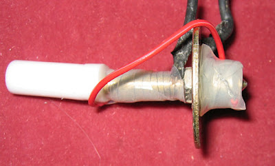
I'm going to throw down some random extruder thoughts, untested theories, and probably re-iterate most of Nophead's proper research. I apologize for any complete rubbish or plagarism
ABS
ABS isn't really like chocolate, or ice, which is a simple solid or liquid.
When cold, it's solid and can withstand quite a lot of force in compression. This allows us to force it down a tube and use it a bit like a rod or piston to force the plastic into the nozzle.
When it warms up, you can bend it easily.
Warm it more, and it starts to soften. Because it's being pushed down, when it gets soft it tries to get wider, pressing against the sides of the tube. At some point, it becomes 'molten'.
'Molten' ABS isn't really liquid. In some ways, it's like plasticine or clay - it needs to be forced through a nozzle, it doesn't really 'flow'.
It's also a bit elasticy at times - when you stop pressing down, it can dribble on slowly for a bit, until it's evened out the pressure.
And finally it's a bit like melted mozzarella - pizza cheese. Pull the melted filament out of a heater, and you often get a really long, thin stringy bit - just like a Domino's advert.
Designing an extruder
Lots of my extruder designs have worked to a greater or lesser extent. It's not *too* hard to make an extruder work once, it's reliability and repeatability that cause my problems.
A larger heater chamber (4mm/5mm diameter) works OK, but the extra ABS takes longer to warm up and melt.
The shorter the 'melted', hot section the better, - preferably as near to the nozzle as you can get. Also, the less metal you have, the less thermal inertia you have, so it heats up quicker. The quicker it heats up, the quicker it cools down while extruding - so the heater power has to be controlled.
PTFE is a good insulator, and it's easy to machine - you can cut an 8mm rod with a sharp craft knife, and it's easy to drill. You can cut a thread easily with a bolt or nut. PEEK is much stronger and requires proper machining - use a tap/die to cut threads.
PTFE is soft, and when it's hot it gets softer, so it really needs extra support (external bolts and washers, etc) to hold the join to the heater barrel still, and extra pressure to avoid leaking plastic out the side. 8mm PEEK rod is strong enough to have a welding tip screw-in (tap an m5 thread) and easily holds the pressure.
The join between the barrel and the insulator is very important. This is where the ABS becomes softer and the filament will get wider and fill any gaps in the channel.
Quite often, my extruder experiments work the first time, but after cooling and re-heating are much stiffer and difficult to get restarted. After inspecting the cold filament, this is because the ABS flows into any small gaps and then solidifes when cold. The entire assembly will then be stuck until the gaps have melted.
If the extruder is hot but not flowing for a long time, the heat will flow up the ABS, softening and widening it further up into the insulator. At least PTFE is very slippery and it helps getting it restarted.
I think NopHead's design, with the thin aluminium tube insulator, excellently avoids the join problem. If you can cool the barrel further up, so that the melt occurs inside the barrel, this problem doesn't occur.
Nichrome / Resistors
Both Nichrome wire and resistors both work reliably and reach the temps needed. Nichrome wire needs more preparation and a layer of insulation - Fire cement, jb weld, or Kapton / kraken tape. If you connect your normal wire to the nichrome by knotting it, or using a crimp connector, it's much easier to wind on and you can hold the join safe inside the fire cement or tape. Nichrome is very flexible, you can wind it on the barrel, nozzle, or both.
Resistors are nice, self-contained heaters. They work well, but you need to transfer the heat from the resistor surface to the nozzle. This means either embedding it in a drilled block (like NopHead) or my low-tech solution of shoving them inside m8 coupling nuts (as I don't have any solid blocks lying around). Either way, they're larger and need more metal (therefore more thermal inertia, slower heater), and not quite as flexible as the assembly is big and chunky compared to the nichrome wire.
Both methods work well.
Nozzles
Ideally, the nozzle should be removable.
Ideally, to keep the heated section as short as possible, the heater should be close to or on the nozzle.
Both of these requirements can conflict :-)
Welding tips (0.6mm) from Halfords, £5 for five, work pretty well as nozzles or even combined barrel/nozzles. They need to be carefully drilled out to 3 or 3.2mm almost to the end, but be careful. I've wrecked four trying to drill to 3.5mm to get a better heater entry, the walls are just too thin. The central hole helps align the drill centrally, even drilling by hand works OK, but I'd use a 1mm then 2mm then 3mm bits first.
I've had reasonable success with a PEEK insulator, a welding tip, with nichrome wire wound directly round the welding tip.
Have a go and see what you think :-)
Thursday, 30 April 2009
More Extruder Experiments
Time to write up the past few weeks of experimenting in making extruders:
This is a quick extruder made from a short section of 5mm brass tube, 8mm PTFE rod with a central 3.2mm hole for the filament and an experimental PTFE nozzle.
The PTFE is drilled about 8mm in to 5mm diameter, and the tube is push-fit into the PTFE.
The nozzle is made from 10mm PTFE rod, drilled almost to the end with a 5mm diameter. Part of the outside is shaped down to 8mm (to fit a large washer for support) and tapered a bit. The final breakthrough was done with a .35mm hand drill where the PTFE is about 2mm thick.
The heater is made from a couple of layers of kraken tape and some (partly) insulated nichrome wire reclaimed from a previous nozzle.
Warming this barrel up, the tape didn't appear to be affected, so I fed some ABS down. it seems to melt fine, filling the 5mm brass easily, but I hadn't bolted it down properly to hold the PTFE together, and I pushed the nozzle off before it came out the 0.35 hole.
It had been at 220C for a half-hour or so, so I deconstructed it to see if the kraken tape was damaged:
It seems to be unaffected. The covering you can see on the nichrome is the original insulation: it seems to decompose and can easily be scraped off with fingers, but even where the nichrome is just bare wire the kraken tape is unaffected. This isn't a long term test, but it's promising.
This extruder uses a brass tube, and a PTFE nozzle and insulator as above, but uses a different heater. Two wirewound resistors are placed inside M8 coupling nuts. The nuts are then held together in a vice and a 5mm hole is drilled between them.
The two coupling nuts can be placed around the brass tube (or even a welding tip) and held together with tape. you can also pop a thermistor between the tape and the nuts for temp monitoring.
To provide pressure to the PTFE tube joints, a large m8 washer is placed over the nozzle (10mm PTFE rod turned town to 8mm) and bolted to the existing BfB extruder drive (using the enhanced coach bolt drive).
This warms up fine to 220C and extrudes with some force. This PTFE nozzle has a 0.6mm hole, about 0.5mm thick PTFE (thin enough to see light through) but is still able to contain reasonably high hand forces. It extrudes, slowly, but immediately expands to a much larger extrusion.
Eventually I decided to re-build a more traditional extruder. A couple of taps with a hammer broke up the fire cement and allowed me to reclaim the nichrome, m6 BfB barrel and nozzle.
Using a combination of learning from my experiments, I've built yet another version:
3ohm nichrome heater directly around the nozzle, and 4ohm above. PTFE screwed to nozzle and also secured using bolts and washer. Washer heat isolated using a turned PTFE washer - also holds the m6 barrel nicely in the m8 washer. kraken tape insulating the heater. Coach bolt hack on a BfB lasercut extruder drive, standard GM3 DC motor/gearbox. Standard BfB aluminium nozzle.
I'll see how this one performs soon... :-)
From Renoir6_Extruder |
The PTFE is drilled about 8mm in to 5mm diameter, and the tube is push-fit into the PTFE.
The nozzle is made from 10mm PTFE rod, drilled almost to the end with a 5mm diameter. Part of the outside is shaped down to 8mm (to fit a large washer for support) and tapered a bit. The final breakthrough was done with a .35mm hand drill where the PTFE is about 2mm thick.
The heater is made from a couple of layers of kraken tape and some (partly) insulated nichrome wire reclaimed from a previous nozzle.
Warming this barrel up, the tape didn't appear to be affected, so I fed some ABS down. it seems to melt fine, filling the 5mm brass easily, but I hadn't bolted it down properly to hold the PTFE together, and I pushed the nozzle off before it came out the 0.35 hole.
From Renoir6_Extruder |
The two coupling nuts can be placed around the brass tube (or even a welding tip) and held together with tape. you can also pop a thermistor between the tape and the nuts for temp monitoring.
To provide pressure to the PTFE tube joints, a large m8 washer is placed over the nozzle (10mm PTFE rod turned town to 8mm) and bolted to the existing BfB extruder drive (using the enhanced coach bolt drive).
From Renoir6_Extruder |
I'll see how this one performs soon... :-)
Friday, 24 April 2009
Don't try this at home
I misused an electric drill to make a temporary lathe.
Using the drill and some scrap wood, I could slide the drill up and down in line with the bit. Very carefully, you can drill holes straight along PTFE or PEEK rod to make an insulator.
I managed to drill a nice straight hole through the PTFE and PEEK.
It seems to work for plastics: I'd definitely get a more secure setup before drilling brass or steel bolts. Even this hacked-together setup is more accurate than (my) drilling 'by hand'
Full story
Saturday, 18 April 2009
Silicone tape
Wandering through a Maplins store the other day, I came across this:
It's silicone tape, and is rated to 260C - high enough for an extruder. One of the suggested uses is for repairing car exhaust systems.
I made a temp extruder heater out of two m8 coupling nuts, two wirewound resistors and a few inches of tape. It seems to hold up well, and went up to 220C.
I need to re-drill some welding tips, since I widened them to 3.5mm and made holes in the sides.
From Renoir5_extruder |
It's silicone tape, and is rated to 260C - high enough for an extruder. One of the suggested uses is for repairing car exhaust systems.
I made a temp extruder heater out of two m8 coupling nuts, two wirewound resistors and a few inches of tape. It seems to hold up well, and went up to 220C.
From Renoir5_extruder |
I need to re-drill some welding tips, since I widened them to 3.5mm and made holes in the sides.
Saturday, 11 April 2009
One step forward, one step back
My jerry-built extruder is blocked.
The coach built drive is still working fine, providing quite a bit of force to the filament - enough to dear big chunks out of it.
The extruder nozzle is blocked.
This happened before, during hand testing. I've restarted and stopped the nozzle several times, and only twice had a jam. Last time, clearing the 0.6mm nozzle hole with a pin did not restart the flow, so it isn't a nozzle blockage. Providing *excessive* force suddenly cleared the blockage and restarted the flow, where it went back to normal.
There is one factor that was the same between blockages.
Both times, immediately before, the filament had been left in the nozzle, and the nozzle had been left hot for several minutes, while testing other stuff. Then the nozzle was turned off and cooled down (end of testing).
The next day, the nozzle was blocked.
On other tests, either the filament was withdrawn while hot, removing the bulk of the plastic, or after extrusion the heater was switched off immediately. Restarting the next day was fine.
I *think* what happens is that the heat travels up the filament, softening and widening it. Over a couple of minutes or so (if it cools immediately) this isn't a problem. If the heat is applied for several minutes, the filament softens further and further up, pressing against the sides of the channel, causing more and more friction. Because my insulator isn't uniform (there is a .3 mm step near the top, and a hole across (see screwdriver drive) this gives plenty of friction - blocking the filament channel. This is why clearing the nozzle doesn't help.
I'd suggest that if you're not using the extruder, or between days, turn the heat off - or better, withdraw the filament an inch or two while hot. My fully assembled extruder worked well, but last time I was testing the axes and trying the sort out a software bug, and I left the extruder hot for 20mins or so while doing so. The next time, it's solidly blocked - no extra force is shifting it. I'll either have to leave it hot for a half-hour or so to see if it softens enough to shift, or disassemble and drill out the stuck filament.
I went out yesterday and bought a small vice (£4.50) and a reamer like Nophead's (£3.00). I'm planning to use the Afghan Lathe technique to make a new extruder insulator with a larger melt chamber (4-5mm?) and a tapered entrance to see if this helps.
Sunday, 5 April 2009
Coach bolt hack working
I ran up the BfB extruder with the coach bolt drive. Drive is a little inconsistent, but works (12mm/sec or more).
It should be enough to let me build another extruder - i.e. RepStrap itself, with a traditional V1 or V2 extruder.
From Coach Bolt drive |
I might try and build a coupler out of polymorph. My solder join is only straightish (a couple of degrees off) because it wasn't held very well while setting. I could also try supergluing a similar reinforcement with the slots - I don't think it will be strong enough on it's own.
I've mounted it on the RepRap
From Coach Bolt drive |
And it should be ready to go soon. I tried using the host software to build a 10x10x10 square, but it started moving the Z-axis down, away fron the endstop. I'm not quite sure why yet... I'll try the replicatorG and the g-code to see if it has the same effect.
MORE DETAILS
Coach Bolt Hack
The M8 bolt in my BfB extruder hasn't been gripping the filament well. I've tried the standard tricks, sharpening the thread, increasing the force (until I cracked the acrylic), but I'm still able to pull the filament out by hand against the thread. While shopping around, I came across some coach bolts with much deeper, sharper threads. Simple replacement of the M8 bolt was difficult - there aren't nuts that fit and it was impossible to attach the existing gear or provide vertical support.
I needed a bolt with m8 at one end for the gear and bearings, and coach bolt screw at the other for the filament bite. So I made this:
It's soldered together ( see pictures for more detail of how), but if I had an extruder I could easily have made a coupler, since the joint is in compression.
It seems to fit OK into the BfB assembly, with a little modification of the bearings (one bearing, rearranged nuts to fit). It grips the filament lovely now, and hand-winding the gear drives the filament well.
I then attached my rebuilt extruder nozzle.
I'll post later when I've tested the nozzle.
I needed a bolt with m8 at one end for the gear and bearings, and coach bolt screw at the other for the filament bite. So I made this:
From Coach Bolt drive |
It's soldered together ( see pictures for more detail of how), but if I had an extruder I could easily have made a coupler, since the joint is in compression.
From Coach Bolt drive |
It seems to fit OK into the BfB assembly, with a little modification of the bearings (one bearing, rearranged nuts to fit). It grips the filament lovely now, and hand-winding the gear drives the filament well.
I then attached my rebuilt extruder nozzle.
From Coach Bolt drive |
I'll post later when I've tested the nozzle.
Subscribe to:
Posts (Atom)